


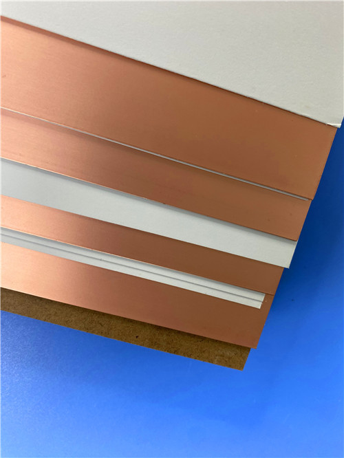

F4BM233 low DK 2.33 PTFE Fiberglass Laminate with ED copper foil and Custom 4mm core thick PCB Solutions
Contact Person : Sally Mao
Phone Number : 86-755-27374847
WhatsApp : +8618277967574
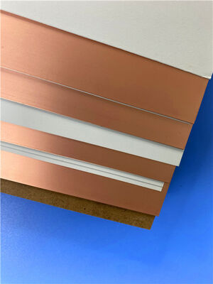
| Brand Name: | Wangling | Model Number: | F4BME300 |
|---|
Product Description
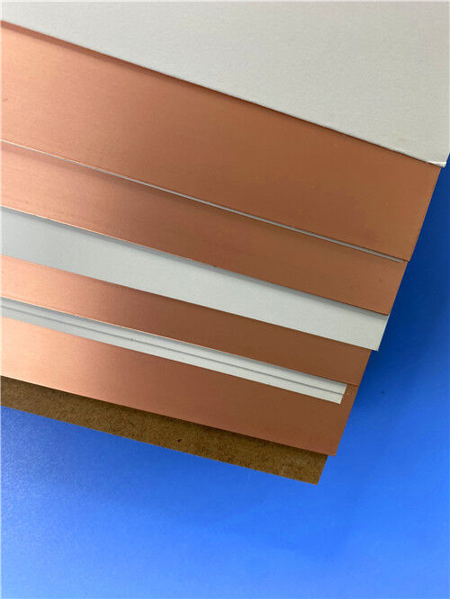
For RF and microwave designs that require low loss, low passive intermodulation (PIM), and stable electrical performance, Wangling’s F4BME300 is a high-performance PTFE composite laminate engineered for demanding antenna and microwave applications. It is precision-formulated from woven fiberglass cloth, PTFE resin, and PTFE film, and is produced under strict process control to deliver consistent electrical properties.
The F4BME300 is part of Wangling’s F4BME series, which uses reverse-treated RTF copper foil. Compared with standard ED-copper F4BM constructions, the RTF foil configuration provides excellent PIM performance, more precise fine-line etching control, and lower conductor loss. The material is positioned as a reliable domestic alternative to comparable imported high-frequency laminates, with improved dielectric loss, insulation resistance, and stability versus earlier F4B products.
Key Properties at a Glance:
| Property | Typical Value | Test Condition |
| Dielectric Constant (Dk) | 3.0 ± 0.06 | 10 GHz |
| Dissipation Factor | 0.0017 / 0.0025 | 10 GHz / 20 GHz |
| Thermal Coefficient of Dk | -80 ppm/°C | -55°C to +150°C |
| CTE - X / Y / Z | 12 / 15 / 95 ppm/°C | -55°C to +288°C |
| PIM | ≤ -159 dBc | F4BME with RTF copper |
| Peel Strength | >1.8 N/mm | 1 oz F4BME |
| Moisture Absorption | ≤0.08% | 20±2°C, 24h |
| Density | 2.29 g/cm³ | Room temperature |
| Thermal Conductivity | 0.42 W/m·K | Z-direction |
| Long-Term Operating Temperature | -55°C to +260°C | High-low temperature chamber |
| Flammability Rating | UL 94 V-0 | — |
Typical values are for material selection reference and do not constitute a warranty. Final material suitability should be verified for each application.
Applications
Custom PCB Manufacturing on F4BME300
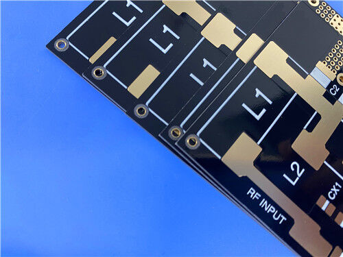
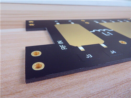
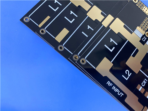
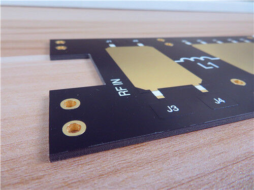
As a specialized manufacturer of high-frequency printed circuit boards, we offer comprehensive fabrication services using Wangling F4BME300 and other advanced laminates. The following specification details a representative 2-layer rigid PCB implementation.
PCB Construction Details:
| Parameter | Specification |
| Base Material | Wangling F4BME300 |
| Layer Count | 2-layer rigid |
| Board Dimensions | 35.65 mm × 68.95 mm per panel, ±0.15 mm |
| Finished Board Thickness | 0.2 mm (as specified) |
| Finished Copper Weight | 1 oz (1.4 mils) outer layers |
| Minimum Trace/Space | 6 / 9 mils |
| Minimum Hole Size | 0.3 mm |
| Via Structure | No blind vias |
| Via Plating Thickness | 20 μm |
| Surface Finish | Immersion Gold |
| Top Solder Mask | Black |
| Bottom Solder Mask | None |
| Top Silkscreen | White |
| Bottom Silkscreen | None |
| Electrical Test | 100% prior to shipment |
| Artwork Format | Gerber RS-274-X |
| Quality Standard | IPC-Class-2 |
Low Loss at Microwave Frequencies:
F4BME300 offers a dissipation factor of 0.0017 at 10 GHz and 0.0025 at 20 GHz, supporting low insertion loss in feed networks, phase shifters, couplers, and antenna distribution circuitry.
Excellent PIM Performance:
When paired with reverse-treated RTF copper foil, F4BME300 achieves PIM values of ≤ -159 dBc. This makes it particularly suitable for base station antennas and other systems where passive intermodulation can limit receive-path sensitivity.
Precise Fine-Line Control:
The RTF copper foil provides more precise etch definition and lower conductor loss than standard ED foil, supporting tighter line-width control for high-precision RF patterns.
Stable Dielectric Performance:
The dielectric constant is tightly controlled at 3.0 ± 0.06 at 10 GHz. The thermal coefficient of Dk is typically -80 ppm/°C from -55°C to +150°C, helping maintain consistent electrical performance over temperature.
Dimensional Stability and CTE:
The material exhibits X/Y CTE values of 12 and 15 ppm/°C over -55°C to +288°C, with a Z-axis CTE of 95 ppm/°C. This supports dimensional stability and reliable plated-through-hole performance in demanding assemblies.
Wide Thickness and Panel Availability:
F4BME300 is available in a broad range of dielectric and total thicknesses, from thin laminates to 12 mm, with standard panel sizes including 460×610 mm, 500×600 mm, 850×1200 mm, 914×1220 mm, and 1000×1200 mm. Custom sizes are available. For Dk 2.7–3.0, the minimum dielectric thickness is 0.2 mm.
Radiation Resistance and Low Outgassing:
The material is suitable for radiation-exposed environments and exhibits low outgassing, making it applicable to satellite, radar, and other high-reliability systems.
Commercial Cost-Effectiveness:
F4BME300 is designed for commercial, high-volume production with a favorable cost-to-performance ratio, while maintaining the electrical and mechanical characteristics required for modern antenna and microwave boards.
Quality and Availability
All boards are manufactured in compliance with IPC-Class-2 quality standards, ensuring robust reliability for commercial, industrial, and communication infrastructure applications. 100% electrical testing is performed prior to shipment to guarantee functional integrity.
Our production capability extends to worldwide availability, with flexible shipping and logistics support for both prototype and volume requirements. We offer rapid turnaround and competitive pricing while maintaining strict process control.
For inquiries about custom stack-ups, panel sizes, RTF copper foil options, aluminum- or copper-backed configurations, or other requirements, please contact our sales engineering team—we are ready to support your high-frequency circuit board requirements.
Enter Your Message

RO4350B, 4003C; Rogers 5880, 5870, 6002, 6010, 6006, 6035; RO3003, RO3035, RO3006, RO3010, RO3210,RO3203
TLX-8, TLX-6, TLX-9, TLX-0, TLX-7, TLY-3, TLY-5, RF-35TC, RF-60TC, RF-35A2, RF-60A, AD450, AD600, TMM4, TC350
| Shenzhen Bicheng Electronics Technology Co., Ltd |
| 6-11C Shidai Jingyuan Fuyong Town, Baoan District, Shenzhen City, Guangdong Province, China |
| 86-755-27374946 |
| sales30@bichengpcb.com |