


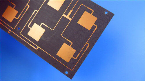
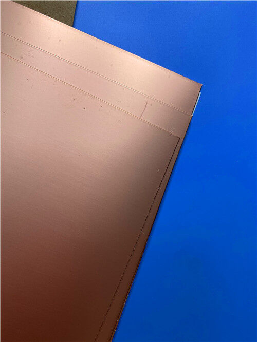
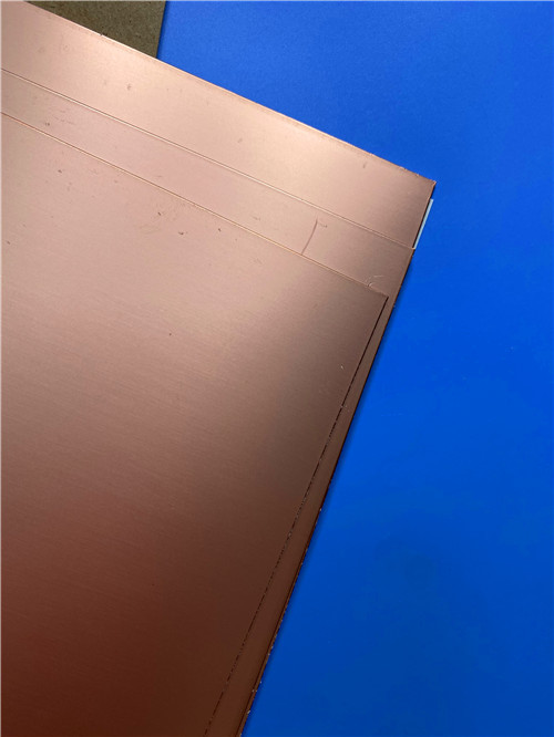

F4BM245 DK2.45 PTFE fiberglass laminate manufacture 2-layer PCB with ED copper foil
Contact Person : Sally Mao
Phone Number : 86-755-27374847
WhatsApp : +8618277967574
| Brand Name: | F4B | Model Number: | F4BME220 |
|---|
Product Description
1. Introduction to F4BME220 High-Frequency Laminate
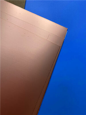
F4BME220 is a premium PTFE fiberglass laminate manufactured by Taizhou Wangling Insulation Material Factory. It is produced through a scientifically formulated process combining fiberglass cloth, polytetrafluoroethylene (PTFE) resin, and PTFE film under strict manufacturing controls. Compared to the earlier F4B series, the F4BME series delivers significantly enhanced electrical performance, including a wider range of dielectric constants, lower dielectric loss, higher insulation resistance, and improved stability, making it a reliable replacement for similar foreign products.
The F4BM and F4BME series share the same dielectric layer but differ in copper foil selection:
| Variant | Copper Foil Type | Key Characteristics |
| F4BM | ED (Electrodeposited) Copper | Suitable for applications without PIM requirements; cost-effective |
| F4BME | Reverse-Treated Foil (RTF) Copper | Excellent PIM performance (≤ -159 dBc); more precise line control; lower conductor loss |
By precisely adjusting the ratio between PTFE resin and fiberglass cloth, Wangling achieves accurate dielectric constant control across a range of 2.17 to 3.0, with customization available. Higher Dk values correspond to higher fiberglass content, resulting in improved dimensional stability, lower CTE, better temperature drift performance, and a slight increase in dielectric loss.
F4BME220 specifically features a dielectric constant of 2.20, offering an optimal balance of ultra-low loss, excellent PIM performance, and cost-effectiveness for high-volume commercial applications.
2. Key Technical Specifications (F4BME220)
| Property | Test Condition | Unit | F4BME220 Value |
| Dielectric Constant (Typical) @ 10 GHz | 10 GHz | — | 2.2 |
| Dielectric Constant Tolerance | — | — | ±0.04 |
| Dissipation Factor (Typical) @ 10 GHz | 10 GHz | — | 0.001 |
| Dissipation Factor (Typical) @ 20 GHz | 20 GHz | — | 0.0014 |
| Thermal Coefficient of Dk | -55°C to +150°C | ppm/°C | -142 |
| Peel Strength (F4BM – 1 oz ED) | — | N/mm | >1.8 |
| Peel Strength (F4BME – 1 oz RTF) | — | N/mm | >1.6 |
| Volume Resistivity | Normal State | MΩ·cm | ≥6×10⁶ |
| Surface Resistivity | Normal State | MΩ | ≥1×10⁶ |
| Electrical Strength (Z-direction) | 5 kV, 500 V/s | kV/mm | >23 |
| Breakdown Voltage (XY-direction) | 5 kV, 500 V/s | kV | >30 |
| CTE – XY direction | -55°C to +288°C | ppm/°C | 25–34 |
| CTE – Z direction | -55°C to +288°C | ppm/°C | 240 |
| Thermal Stress | 260°C, 10s, 3 cycles | — | No Delamination |
| Moisture Absorption | 20±2°C, 24 hours | % | ≤0.08 |
| Density | Room Temperature | g/cm³ | 2.18 |
| Long-Term Operating Temperature | — | °C | -55 to +260 |
| Thermal Conductivity (Z-direction) | — | W/(m·K) | 0.24 |
| PIM Value (F4BME only) | — | dBc | ≤ -159 |
| Flammability | — | UL-94 | V-0 |
| Material Composition | — | — | PTFE + Fiberglass Cloth + RTF Copper Foil |
Note: F4BME uses RTF (Reverse-Treated Foil) copper foil; F4BM uses ED copper foil.
3. Features & Benefits
F4BME220 delivers a comprehensive set of advantages for high-frequency circuit designs:
| Feature | Description |
| Wide Dk Range (2.17 – 3.0) | Selectable and customizable dielectric constants to meet diverse design requirements |
| Ultra-Low Dissipation Factor | 0.0010 @ 10 GHz – among the lowest in its class |
| RTF Copper Foil | Reverse-treated foil provides excellent PIM performance (≤ -159 dBc) |
| Low Thermal Coefficient of Dk | -142 ppm/°C ensures stable performance across temperature |
| UL 94 V-0 Flammability | Meets stringent safety requirements |
| Diversified Sizes | Multiple standard and custom panel sizes available |
Excellent PIM Performance: F4BME's RTF copper foil delivers PIM values ≤ -159 dBc, ensuring clean signal transmission in demanding RF systems.
Ultra-Low Loss: With a dissipation factor of just 0.0010 at 10 GHz, F4BME220 minimizes insertion loss for high-efficiency designs.
Enhanced Stability: Tight Dk tolerance (±0.04) and low moisture absorption (≤0.08%) ensure consistent electrical performance.
Radiation Resistance & Low Outgassing: Suitable for aerospace and space applications.
Cost-Effective: Commercial-grade, high-volume production with excellent price-to-performance ratio.
Dimensional Stability: Optimized PTFE-to-fiberglass ratio provides excellent dimensional stability and low thermal expansion.
Versatile Processing: Supports standard PCB manufacturing processes with demonstrated excellent machinability for fine-line circuits and dense hole patterns.
Commercial Availability: Mass production capability with diversified sizes to optimize material utilization and reduce costs.
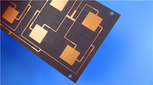
4. Custom Ultra-Thin 2-Layer PCB Solution on F4BME220
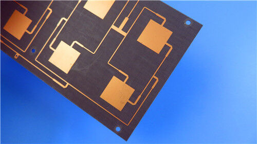
Leveraging the advanced properties of F4BME220, we offer the following precision-engineered ultra-thin 2-layer rigid PCB solution. This design is ideal for space-constrained RF, microwave, and antenna applications requiring exceptional electrical performance and mechanical flexibility.
PCB Construction Details
| Parameter | Specification |
| Base Material | Wangling F4BME220 (RTF Copper) |
| Number of Layers | 2 |
| Finished Board Size | 79 mm × 65.3 mm (±0.15 mm) |
| Finished Board Thickness | 0.1 mm (Ultra-Thin) |
| Minimum Trace / Space | 5 / 8 mils |
| Minimum Hole Size | 0.25 mm (through-hole only; no blind vias) |
| Outer Layer Copper Weight | 1 oz (35 μm) |
| Via Plating Thickness | 20 μm |
| Surface Finish | Immersion Gold (ENIG) |
| Top Silkscreen | White |
| Bottom Silkscreen | None |
| Top Solder Mask | Green |
| Bottom Solder Mask | None |
| Electrical Testing | 100% prior to shipment |
| Accepted Quality Standard | IPC-Class-2 |
| Artwork Format | Gerber RS-274-X |
| Global Availability | Worldwide shipping |
Design & Manufacturing Highlights
Ultra-Thin Profile: At just 0.1 mm finished thickness with a 0.1 mm core, this PCB offers an exceptionally low-profile, lightweight solution—one of the thinnest available in the industry—ideal for compact portable devices, flexible assemblies, and space-constrained RF modules.
Fine-Feature Capability: Supports 5/8 mil trace/space and 0.25 mm micro-vias, enabling dense, high-frequency circuit layouts with excellent signal integrity.
Low-Loss Copper Layers: 1 oz (35 μm) RTF copper on both sides provides excellent conductivity with reduced conductor loss and superior PIM performance.
Green Solder Mask on Top: Provides protection for the top copper layer while allowing visual inspection and assembly.
Reliable Interconnects: The Immersion Gold surface finish delivers a flat, oxidation-resistant, and highly solderable surface, ensuring robust component attachment and long-term reliability.
Excellent PTH Reliability: With 20 μm via plating, the PCB offers reliable plated-through-hole integrity despite the ultra-thin construction.
Strict Quality Control: Every board undergoes 100% electrical testing and is manufactured to IPC-Class-2 standards, guaranteeing consistent quality and performance.
Critical Design Considerations
Due to the ultra-thin 0.1 mm dielectric thickness, this PCB design requires careful handling during fabrication and assembly. Key considerations include:
Minimized Warpage: Special processing techniques are employed to maintain flatness during lamination and soldering.
Precision Etching: Fine-feature capability (5/8 mil) demands high-resolution etching processes.
Controlled Impedance: The thin dielectric enables tight impedance control for high-frequency designs.
Panel Size Limitation: For thicknesses ≤0.2 mm, the maximum panel size is restricted to 500×610 mm to maintain processing yield and quality.
5. Typical Applications
F4BME220 and its ultra-thin PCB implementation are ideal for a wide range of high-frequency and space-constrained applications:
Microwave, RF & Radar Systems: High-frequency signal processing and transmission modules.
Phase Shifters: Precision phase control for beamforming and phased arrays.
Power Dividers, Couplers & Combiners: Power distribution and combining networks.
Feed Networks: Signal distribution for antenna arrays.
Phased Array Antennas: Compact, lightweight antenna elements for radar and communications.
Satellite Communications: Spaceborne and ground-based satellite equipment requiring low outgassing.
Base Station Antennas: Mobile communications infrastructure.
Passive Components: Filters, mixers, and other passive RF devices.
6. Conclusion
As a specialized supplier of custom high-frequency circuit boards, we combine the proven performance of Wangling F4BME220 – a commercial-grade, ultra-low-loss PTFE fiberglass laminate with excellent PIM performance – with our precision manufacturing capabilities to deliver world-class PCB solutions. Our ultra-thin 2-layer offering fully leverages F4BME220's stable dielectric properties, ultra-low loss (0.0010 @ 10 GHz), excellent PIM performance (≤ -159 dBc), and dimensional stability, ensuring your most demanding RF, microwave, and antenna designs achieve optimal performance in the most compact form factors.
Whether you are developing phased array antennas, satellite communication equipment, base station infrastructure, or compact RF modules, our engineering team is ready to support your project. For technical consultations, samples, or volume orders, please contact us today. We look forward to being your trusted partner in high-frequency innovation.
Enter Your Message

RO4350B, 4003C; Rogers 5880, 5870, 6002, 6010, 6006, 6035; RO3003, RO3035, RO3006, RO3010, RO3210,RO3203
TLX-8, TLX-6, TLX-9, TLX-0, TLX-7, TLY-3, TLY-5, RF-35TC, RF-60TC, RF-35A2, RF-60A, AD450, AD600, TMM4, TC350
| Shenzhen Bicheng Electronics Technology Co., Ltd |
| 6-11C Shidai Jingyuan Fuyong Town, Baoan District, Shenzhen City, Guangdong Province, China |
| 86-755-27374946 |
| sales30@bichengpcb.com |