



F4BTME350 Ceramic-Filled PTFE Laminate with Reverse-Treated Copper and Custom 2-layer PCB built on 10mil substrate material for RF Microwave
Contact Person : Sally Mao
Phone Number : 86-755-27374847
WhatsApp : +8618277967574
| Brand Name: | Wangling | Model Number: | F4BTMS220 |
|---|
Product Description
For aerospace and defense RF systems, material performance is not just about electrical characteristics—it is about surviving the vacuum of space, the vibration of launch, and the temperature extremes of flight while maintaining phase stability and low loss. The F4BTMS220 from Taizhou Wangling Insulation Materials Factory represents the pinnacle of this material class: an aerospace-grade, ceramic-filled PTFE laminate engineered to replace comparable foreign products with superior reliability and performance.
The F4BTMS series is an upgraded version of the F4BTM series, achieving a technological breakthrough in material formulation and manufacturing processes. By incorporating a large amount of uniformly distributed special nano-ceramics mixed with PTFE resin, and reinforced with ultra-thin, ultra-fine glass fiber cloth, the material minimizes glass fiber effects on electromagnetic wave propagation, reduces dielectric loss, and enhances dimensional stability. The result is a material with reduced X/Y/Z anisotropy, higher usable frequency range, improved electrical strength, and better thermal conductivity.
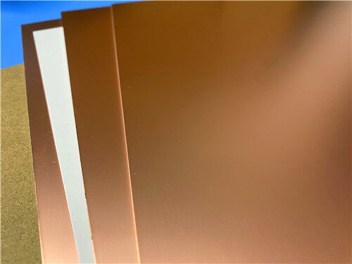
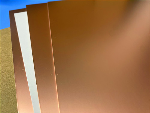
The F4BTMS series comes standard with RTF low-roughness copper foil, reducing conductor loss while providing excellent peel strength. It can be paired with copper or aluminum bases, and F4BTMS294 can be combined with 50Ω resistive copper foil to form resistive laminates. The material processes using standard PTFE board fabrication techniques and is suitable for multilayer, high-layer-count, and backplane processing, with excellent machinability for dense vias and fine traces.
| Product Technical Parameters | Product Models & Data Sheet | ||||||||||||
| Product Features | Test Conditions | Unit | F4BTMS220 | F4BTMS233 | F4BTMS255 | F4BTMS265 | F4BTMS294 | F4BTMS300 | F4BTMS350 | F4BTMS430 | F4BTMS450 | F4BTMS615 | F4BTMS1000 |
| Dielectric Constant (Typical) | 10GHz | / | 2.2 | 2.33 | 2.55 | 2.65 | 2.94 | 3.00 | 3.50 | 4.30 | 4.50 | 6.15 | 10.20 |
| Dielectric Constant Tolerance | / | / | ±0.02 | ±0.03 | ±0.04 | ±0.04 | ±0.04 | ±0.04 | ±0.05 | ±0.09 | ±0.09 | ±0.12 | ±0.2 |
| Dielectric Constant (Design) | 10GHz | / | 2.2 | 2.33 | 2.55 | 2.65 | 2.94 | 3.0 | 3.50 | 4.3 | 4.5 | 6.15 | 10.2 |
| Loss Tangent (Typical) | 10GHz | / | 0.0009 | 0.0010 | 0.0012 | 0.0012 | 0.0012 | 0.0013 | 0.0016 | 0.0015 | 0.0015 | 0.0020 | 0.0020 |
| 20GHz | / | 0.0010 | 0.0011 | 0.0013 | 0.0014 | 0.0014 | 0.0015 | 0.0019 | 0.0019 | 0.0019 | 0.0023 | 0.0023 | |
| 40GHz | / | 0.0013 | 0.0015 | 0.0016 | 0.0018 | 0.0018 | 0.0019 | 0.0024 | 0.0024 | 0.0024 | / | / | |
| Dielectric Constant Temperature Coefficient | -55 º~150ºC | PPM/℃ | -130 | -122 | -92 | -88 | -20 | -20 | -39 | -60 | -58 | -96 | -320 |
| Peel Strength | 1 OZ RTF copper | N/mm | >2.4 | >2.4 | >1.8 | >1.8 | >1.2 | >1.2 | >1.2 | >1.2 | >1.2 | >1.2 | >1.2 |
| Volume Resistivity | Standard Condition | MΩ.cm | ≥1×10^8 | ≥1×10^8 | ≥1×10^8 | ≥1×10^8 | ≥1×10^8 | ≥1×10^8 | ≥1×10^8 | ≥1×10^8 | ≥1×10^8 | ≥1×10^8 | ≥1×10^8 |
| Surface Resistivity | Standard Condition | MΩ | ≥1×10^8 | ≥1×10^8 | ≥1×10^8 | ≥1×10^8 | ≥1×10^8 | ≥1×10^8 | ≥1×10^8 | ≥1×10^8 | ≥1×10^8 | ≥1×10^8 | ≥1×10^8 |
| Electrical Strength (Z direction) | 5KW,500V/s | KV/mm | >26 | >30 | >32 | >34 | >40 | >40 | >42 | >44 | >45 | >48 | >23 |
| Breakdown Voltage (XY direction) | 5KW,500V/s | KV | >35 | >38 | >40 | >42 | >48 | >52 | >55 | >52 | >54 | >55 | >42 |
| Coefficientof Thermal Expansion (X, Y direction) | -55 º~288ºC | ppm/ºC | 40, 50 | 35, 40 | 15, 20 | 15, 20 | 10, 12 | 10, 11 | 10, 12 | 13, 12 | 12, 12 | 10, 12 | 16, 18 |
| Coefficientof Thermal Expansion (Z direction) | -55 º~288ºC | ppm/ºC | 290 | 220 | 80 | 72 | 22 | 22 | 20 | 47 | 45 | 40 | 32 |
| Thermal Stress | 260℃, 10s,3 times | / | No delamination | No delamination | No delamination | No delamination | No delamination | No delamination | No delamination | No delamination | No delamination | No delamination | No delamination |
| Water Absorption | 20±2℃, 24 hours | % | 0.02 | 0.02 | 0.025 | 0.025 | 0.02 | 0.025 | 0.03 | 0.08 | 0.08 | 0.1 | 0.03 |
| Density | Room Temperature | g/cm3 | 2.18 | 2.22 | 2.26 | 2.26 | 2.25 | 2.28 | 2.3 | 2.51 | 2.53 | 2.75 | 3.2 |
| Long-Term Operating Temperature | High-Low Temperature Chamber | ℃ | -55~+260 | -55~+260 | -55~+260 | -55~+260 | -55~+260 | -55~+260 | -55~+260 | -55~+260 | -55~+260 | -55~+260 | -55~+260 |
| Thermal Conductivity | Z direction | W/(M.K) | 0.26 | 0.28 | 0.31 | 0.36 | 0.58 | 0.58 | 0.6 | 0.63 | 0.64 | 0.67 | 0.81 |
| Flammability | / | UL-94 | V-0 | V-0 | V-0 | V-0 | V-0 | V-0 | V-0 | V-0 | V-0 | V-0 | V-0 |
| Material Composition | / | / | PTFE,Ultra-thin and ultra-fine (quartz) fiberglass. | PTFE,Ultra-thin and ultra-fine fiberglass, ceramics. | |||||||||
Applications
Custom PCB Manufacturing on F4BTMS220
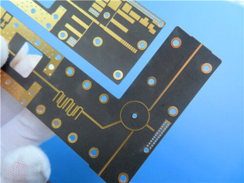
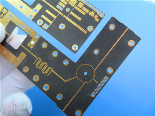
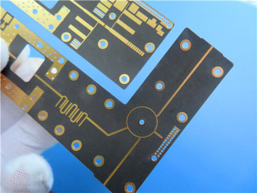
As a specialized manufacturer of high-frequency printed circuit boards, we offer comprehensive fabrication services using F4BTMS220 and other advanced materials. The following specification details a representative 2-layer rigid PCB implementation:
PCB Construction Details:
| Parameter | Specification |
| Base Material | F4BTMS220 |
| Layer Count | 2-layer rigid |
| Board Dimensions | 36.4mm × 88.76mm per panel, ±0.15mm |
| Finished Thickness | 0.3mm |
| Copper Weight | 1 oz (1.4 mils) outer layers |
| Minimum Trace/Space | 6 / 7 mils |
| Minimum Hole Size | 0.4mm |
| Via Structure | No blind or buried vias |
| Via Plating Thickness | 20 μm |
| Surface Finish | Immersion Gold |
| Solder Mask | None (bare substrate) |
| Silkscreen | None |
| Electrical Test | 100% prior to shipment |
| Artwork Format | Gerber RS-274-X |
| Quality Standard | IPC-Class-2 |
Ultra-Low Loss Across Broad Frequency Range:
F4BTMS220 delivers exceptional loss performance with a dissipation factor of 0.0009 at 10 GHz, 0.0010 at 20 GHz, and 0.0013 at 40 GHz. The material maintains stable Dk and low loss from 0.5 to 40 GHz, meeting the demands of phase-sensitive applications across multiple frequency bands.
Tight Dk Tolerance and Batch Consistency:
With a Dk of 2.2 ± 0.02 at 10 GHz, F4BTMS220 offers excellent batch-to-batch consistency, ensuring repeatable circuit performance and minimizing tuning requirements in production.
Excellent Temperature Stability:
The dielectric constant temperature coefficient of -130 ppm/°C over -55°C to +150°C provides stable frequency and phase performance across temperature. The material's usable temperature range far exceeds this window, supporting operation from -55°C to +260°C.
Aerospace-Grade Reliability:
F4BTMS220 exhibits excellent radiation resistance, maintaining stable dielectric and physical properties after radiation exposure. Its low outgassing performance meets aerospace vacuum outgassing requirements, making it suitable for space and cabin equipment.
Superior Dimensional Stability:
The ultra-thin, ultra-fine glass fiber reinforcement combined with nano-ceramics reduces X/Y/Z anisotropy and provides excellent dimensional stability. This ensures thermal dimensional stability and plated through-hole reliability.
Enhanced Thermal Management:
A thermal conductivity of 0.26 W/m·K in the Z-direction supports heat dissipation in higher-power applications, while the low CTE in X/Y directions (40/50 ppm/°C) ensures compatibility with copper expansion.
Low Moisture Absorption:
At 0.02%, F4BTMS220 absorbs minimal moisture, maintaining stable electrical properties in humid environments and ensuring reliable performance in diverse operating conditions.
Metal-Backed Options:
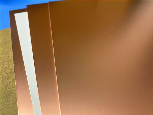
The material can be supplied with copper or aluminum bases (F4BTMS—CU or F4BTMS—AL) for shielding or heat dissipation, with metal base thicknesses from 0.48 mm to 3.98 mm and panel sizes up to 460×610mm.
Standard RTF Copper Foil:
RTF low-roughness copper foil comes standard, reducing conductor loss while providing excellent peel strength (>2.4 N/mm for 1 oz RTF).
Quality and Availability
All boards are manufactured in compliance with IPC-Class-2 quality standards, ensuring robust reliability for commercial, industrial, and aerospace applications. 100% electrical testing is performed prior to shipment to guarantee functional integrity.
Our production capability extends to worldwide availability, with flexible shipping and logistics support for both prototype and volume requirements. We offer rapid turnaround and competitive pricing while maintaining strict process control.
For inquiries about custom stack-ups, panel sizes, metal-backed options (copper or aluminum), resistive copper foil configurations, or other requirements, please contact our sales engineering team—we are ready to support your high-frequency circuit board requirements.
Enter Your Message

RO4350B, 4003C; Rogers 5880, 5870, 6002, 6010, 6006, 6035; RO3003, RO3035, RO3006, RO3010, RO3210,RO3203
TLX-8, TLX-6, TLX-9, TLX-0, TLX-7, TLY-3, TLY-5, RF-35TC, RF-60TC, RF-35A2, RF-60A, AD450, AD600, TMM4, TC350
| Shenzhen Bicheng Electronics Technology Co., Ltd |
| 6-11C Shidai Jingyuan Fuyong Town, Baoan District, Shenzhen City, Guangdong Province, China |
| 86-755-27374946 |
| sales30@bichengpcb.com |