


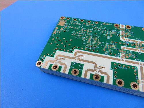
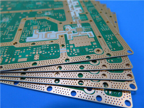
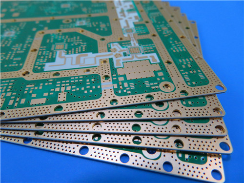
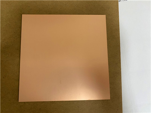

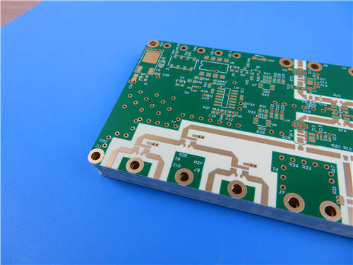
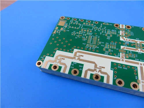
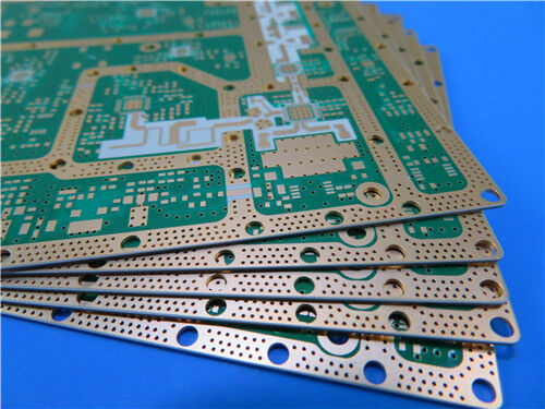
8-Layer RO4350B + Isola I-Tera® MT40 multilayer Hybrid RF PCB with blind vias (L1–L2, L7–L8) and 50Ω single-ended impedance control withstand multiple SMT reflow soldering cycles
Contact Person : Sally Mao
Phone Number : 86-755-27374847
WhatsApp : +8618277967574
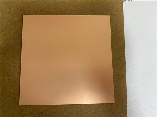
| Brand Name: | Rogers | Model Number: | RO4350B + Tg170 TU-768 FR4 |
|---|
Product Description
This article presents a detailed design strategy for a 10-layer hybrid RF PCB that combines the exceptional high-frequency performance of Rogers RO4350B™ on both the top and bottom layers with the high thermal reliability and cost-effectiveness of Tg170 TU-768 FR4 in the inner layers.
This hybrid construction is specifically engineered to meet the demands of complex RF/microwave modules requiring symmetric high-frequency performance, multiple SMT reflow cycles, and reliable thermal management in a robust 2.5mm-thick form factor. By integrating RO4350B as the outer-layer high-frequency material and TU-768 FR4 as the internal bonding/core layers, this design achieves an optimal balance of electrical performance, mechanical robustness, and manufacturability for mass production.
Rogers RO4350B™ High-Frequency Laminate
RO4350B™ is a hydrocarbon ceramic laminate from Rogers Corporation's RO4000® series, designed to offer superior high-frequency performance and low-cost circuit fabrication. It is a low-loss material that can be fabricated using standard epoxy/glass (FR-4) processes at competitive prices.
Key Features:
Key Specifications (RO4350B):
| Property | Typical Value | Unit | Test Condition |
| Dielectric Constant (Dk) | 3.48 ± 0.05 | — | 10 GHz / 23°C |
| Dissipation Factor (Df) | 0.0037 | — | 10 GHz / 23°C |
| Tg | >280 | °C | TMA |
| CTE – X axis | 14 | ppm/°C | -55 to 288°C |
| CTE – Y axis | 16 | ppm/°C | -55 to 288°C |
| CTE – Z axis | 32 | ppm/°C | -55 to 288°C |
| Thermal Conductivity | 0.69 | W/(m·K) | 80°C |
| Moisture Absorption | 0.06 | % | D48/50 |
| Density | 1.86 | g/cm³ | — |
| Flammability | V-0 | — | UL 94 |
| Lead-Free Process Compatible | Yes | — | — |
Tg170 TU-768 FR4 High-Thermal-Relability Laminate
TU-768 is a high-performance FR-4 laminate with a Tg of 170°C, designed for multilayer Printed Wiring Board (PWB) applications requiring maximum thermal performance and reliability. It is manufactured with a high-performance multifunctional epoxy resin, reinforced with electrical grade (E-glass) glass fabric.
Key Features:
Key Specifications (TU-768):
| Property | Typical Value | Unit | Test Method |
| Tg | 170 | °C | DSC |
| Td (5% weight loss) | 340 | °C | TGA |
| CTE – Z-axis (Pre-Tg) | 45 | ppm/°C | — |
| CTE – X/Y axis (Pre-Tg) | 13/14 | ppm/°C | — |
| Thermal Conductivity | 0.4 | W/(m·K) | — |
| Dk @ 1 GHz | 4.17 | — | IPC-TM-650 2.5.5.9 |
| Df @ 1 GHz | 0.0161 | — | IPC-TM-650 2.5.5.9 |
| Moisture Absorption | 0.15 | % | — |
| Flammability | V-0 | Rating | UL 94 |
RF Design Value of the Dual-Sided 10mil RO4350B High-Frequency Substrates
The top and bottom layers utilize 10mil (0.254mm) RO4350B low-loss ceramic dielectric, which offers a low dissipation factor (Df 0.0037 at 10 GHz) and minimal dielectric loss. This effectively suppresses microwave and RF signal transmission loss, ensuring stable impedance for surface-layer RF traces.
The 10mil dielectric thickness provides ample space for wide-range impedance tuning, making it adaptable to various RF transceiver module circuits. The dual-sided high-frequency substrate layout ensures that the top and bottom signal layers have symmetric performance, reducing overall electromagnetic interference (EMI) across the entire board.
Cost and Thermal Balance Advantages of Tg170 TU-768 FR4 in the Middle Layers
The middle layers use TU-768 high-Tg FR4 to replace expensive RO4350B, significantly reducing material costs for the 10-layer board and making it suitable for mass production.
The Tg170 high-thermal-resistance substrate withstands multiple SMT reflow cycles and resists thermal delamination, solving the poor thermal stability and warpage issues associated with pure ceramic multilayer boards. The FR4 substrate's high mechanical strength supports the 2.5mm-thick 10-layer large-board structure, improving the overall flatness of the board.
Lamination Control Challenges for 2.5mm-Thick 10-Layer Hybrid Boards
The 10-layer structure with a large total thickness and CTE mismatch between RO4350B and FR4 requires gradient heating and segmented dwell lamination profiles—these are essential for reliable bonding.
Thick boards are prone to layer misalignment and uneven dielectric compression, requiring additional registration targets and uniform pressure pads. Cumulative thickness tolerance control across the multilayer stackup is critical to ensure the finished product consistently meets the 2.5mm standard thickness.
PCB Construction Details
| Parameter | Specification |
| Base Material (High-Frequency Layers) | Rogers RO4350B (10 mil) – Top and Bottom |
| Base Material (Inner Layers) | Tg170 TU-768 FR4 |
| Number of Layers | 10 |
| Finished Board Size | 132 mm × 76.5 mm (1 piece, including process edges) |
| Finished Board Thickness | 2.5 mm |
| Outer Layer Copper Weight | 1 oz (35 μm) |
| Inner Layer Copper Weight | 1 oz (35 μm) |
| Via Plating Thickness | 25 μm |
| Surface Finish | Immersion Gold (140%–150%) |
| Top Solder Mask | Green |
| Bottom Solder Mask | Green |
| Top Silkscreen | White |
| Bottom Silkscreen | White |
| Via Plugging | Resin-filled and plated flat |
| Electrical Testing | 100% prior to shipment |
| Accepted Quality Standard | IPC 6012D CLASS-3 |
| Artwork Format | Gerber RS-274-X |
| Global Availability | Worldwide shipping |
PCB Stackup
Resin-Filled and Plated-Flat Vias
The vias are resin-filled and plated flat (also known as via plugging with conductive or non-conductive resin followed by copper plating). This provides a flat, planar surface for subsequent lamination and assembly, ensuring reliable interconnection and preventing via-induced defects. The 25 μm via plating thickness ensures robust electrical connection.
Immersion Gold (140%–150%)
The immersion gold finish (140%–150% gold thickness) provides a flat, oxidation-resistant, and highly solderable surface with excellent wire-bonding capability. The 140%–150% specification refers to the gold thickness, ensuring robust protection against corrosion and wear.
Features & Benefits Summary
| Feature | Benefit |
| Hybrid RO4350B + TU-768 FR4 Construction | Optimizes high-frequency performance and cost-effectiveness |
| 10-Layer Design | Supports complex RF/microwave circuits with power/ground planes |
| 10mil RO4350B Top and Bottom Layers | Low loss (Df 0.0037) for symmetric RF signal transmission |
| TU-768 High-Tg FR4 Inner Layers | High Tg (170°C), excellent thermal reliability, cost-effective |
| Resin-Filled and Plated-Flat Vias | Provides planar surface for reliable lamination and assembly |
| 25 μm Via Plating | Robust electrical connection |
| Immersion Gold (140%–150%) | Flat, solderable, wire-bondable, and corrosion-resistant |
| Green Solder Mask / White Silkscreen | Comprehensive protection with clear component identification |
| 2.5mm Finished Thickness | Robust mechanical support for large-board designs |
| IPC 6012D CLASS-3 | Highest reliability standard for demanding applications |
| 100% Electrical Testing | Guaranteed quality and performance |
Typical Applications
This 10-layer hybrid PCB is ideal for a wide range of high-performance applications:
Conclusion
As a specialized supplier of custom high-frequency circuit boards, we combine the proven performance of Rogers RO4350B (low loss, stable Dk, excellent dimensional stability) and Tg170 TU-768 FR4 (high Tg, excellent thermal reliability, cost-effective) with our precision manufacturing capabilities to deliver world-class hybrid PCB solutions.
The 10-layer hybrid offering fully leverages RO4350B's low-loss high-frequency performance and TU-768's thermal reliability and processing advantages, while incorporating advanced features such as resin-filled and plated-flat vias, 25 μm via plating, and IPC 6012D CLASS-3 manufacturing standards to ensure optimal signal integrity and reliability in a 2.5mm form factor.
Whether you are developing phased array antennas, cellular infrastructure equipment, automotive radar modules, or satellite communication payloads, our engineering team is ready to support your project. For technical consultations, samples, or volume orders, please contact us today. We look forward to being your trusted partner in high-frequency innovation.
Enter Your Message

RO4350B, 4003C; Rogers 5880, 5870, 6002, 6010, 6006, 6035; RO3003, RO3035, RO3006, RO3010, RO3210,RO3203
TLX-8, TLX-6, TLX-9, TLX-0, TLX-7, TLY-3, TLY-5, RF-35TC, RF-60TC, RF-35A2, RF-60A, AD450, AD600, TMM4, TC350
| Shenzhen Bicheng Electronics Technology Co., Ltd |
| 6-11C Shidai Jingyuan Fuyong Town, Baoan District, Shenzhen City, Guangdong Province, China |
| 86-755-27374946 |
| sales30@bichengpcb.com |