


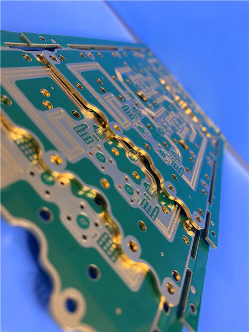

RO4350B + RO3010 Hybrid PCB What Makes This 12-Layer High-Frequency Board Ideal for RF & Radar Applications?
Contact Person : Sally Mao
Phone Number : 86-755-27374847
WhatsApp : +8618277967574
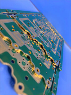
| Brand Name: | Rogers | Model Number: | RO4350B+IT-180A |
|---|
Product Description
Copper Foils for High-Frequency Circuit Materials – Selection Guide for Low-Loss PCB Design
Q: Why does copper foil selection matter for high-frequency PCBs?
A: The surface roughness of copper foil is a critical factor affecting signal integrity in high-frequency designs, particularly above 1 GHz. Roughness forces high-frequency current—which concentrates near the conductor surface due to the skin effect—to travel a longer effective path, converting electromagnetic energy into heat and increasing insertion loss .
At millimeter-wave frequencies, standard electrodeposited (ED) foil can double or triple conductor loss compared to smooth foils . For your 6-layer hybrid PCB combining RO4350B (RF layers) and IT-180A (core layers), selecting the right copper foil is essential to achieve the low-loss performance required for 5G and microwave applications.
1. Copper Foil Manufacturing – ED vs. Rolled
Copper foils for PCB laminates are manufactured through two fundamentally different processes, resulting in distinct surface characteristics and electrical performance.
Electrodeposited (ED) Copper
In the ED process, copper is electrochemically deposited onto a rotating titanium drum from a copper sulfate solution. The drum side (smooth) faces the dielectric, while the matte side (rough) faces outward. The matte side undergoes additional treatment to enhance adhesion .
Crystal Structure: ED copper crystals grow lengthwise in the Z-axis of the foil, forming a "picket fence" structure with long crystal boundaries perpendicular to the foil plane .
Roughness: ED foils typically have higher surface roughness (Rz = 5–12 µm) compared to rolled copper, with the treated side being significantly rougher than the drum side.
Advantage: Lower cost and wider availability.
Rolled Copper
Rolled copper is produced by successive cold rolling operations to reduce thickness, starting from a pure copper billet. The surface smoothness depends on the rolling mill condition.
Crystal Structure: Rolled copper crystals are broken and crushed during cold rolling, resulting in smaller, irregular, spherical shapes aligned nearly parallel to the foil plane .
Roughness: Rolled copper is typically the smoothest copper foil type, with very low profile (Rz < 3 µm) .
Advantage: Superior for high-frequency applications due to smooth surface and excellent elongation.
2. Copper Roughness – The Key Loss Mechanism
At DC, current distributes uniformly through the conductor cross-section. As frequency increases, current crowds toward the conductor surface.
The skin depth δ is:
δ = 1 / √(π·f·µ·σ)
At 10 GHz in copper, δ ≈ 0.66 µm.
Roughness-to-Skin-Depth Ratio
The critical parameter is the ratio of RMS roughness to skin depth (Rrms/δ). As frequency increases and skin depth shrinks, the roughness becomes proportionally larger :
| Ratio (Rrms/δ) | Impact on Loss |
| < 0.1 | Negligible effect (<2% additional loss) |
| 0.1 to 1.0 | Moderate impact (10–50% additional loss) |
| > 1.0 | Severe impact (50–100%+ additional loss) |
For standard ED foil (Rrms ≈ 3–4 µm), the ratio exceeds 1.0 above ~5 GHz – precisely the operating range of modern 5G and millimeter-wave systems .
The Hall-Huray Model
The IPC and IEEE communities have adopted the Huray "snowball" model as the most physically accurate roughness correction factor. Unlike the older Hammerstad model (which saturates at a 2× correction factor), the Huray model represents the rough surface as a collection of spherical protrusions and accurately predicts roughness loss factors of 2.5–3.5× at millimeter-wave frequencies for standard foil .
3. Copper Foil Roughness Measurements
Rogers uses white light interferometry to characterize copper foil roughness, reporting the Sq (RMS) profile. Studies show that the treated side profile correlates best with conductor losses .
Typical Roughness Values by Foil Type
| Foil Type | Weight | Dielectric Side Sq (µm) | Top Side Sq (µm) | Products |
| Rolled | 1 oz | 0.4 | 0.3 | RT/duroid, RO3003, RO3035, 6202 |
| Rolled | ½ oz | 0.4 | 0.3 | Same as above |
| ED (RO4350B) | 1 oz | 3.2 | 0.4 | RO4350B, RO4003C, RO4360G2 |
| ED (RO4350B) | ½ oz | 2.8 | 0.4 | RO4350B, RO4003C |
| LoPro® | 1 oz | 0.9 | 1.3 | RO4003C, RO4350B, RO4835 |
| LoPro® | ½ oz | 0.9 | 0.8 | RO4003C, RO4350B, RO4835 |
| ED Low Profile RT | 1 oz | 1 | 1.3 | CLTE, DiClad, IsoClad |
| ED Low Profile RT | ½ oz | 1 | 0.8 | CLTE, DiClad, IsoClad |
Source: Rogers Corporation copper foils data sheet
Key Insight: The dielectric side roughness (the surface bonded to the laminate) is the primary contributor to conductor loss. Rolled copper (Sq = 0.4 µm) offers the smoothest surface, while standard ED foil on RO4350B (Sq = 2.8–3.2 µm) has significantly higher roughness.
4. Hybrid Stack-Up Foil Considerations
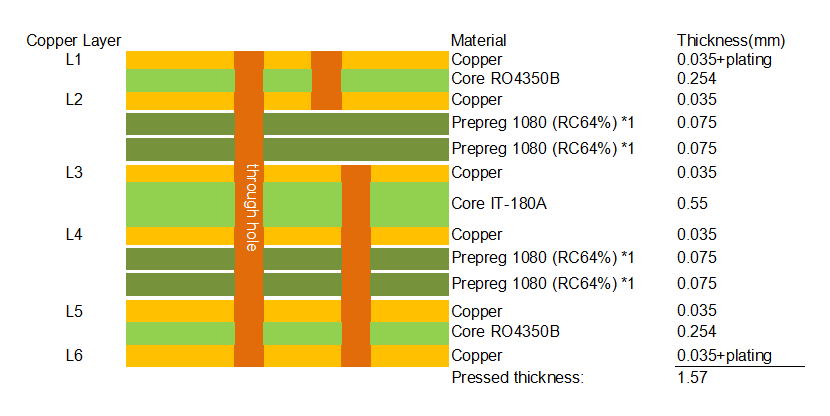
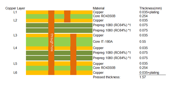
Your 6-layer board uses a RO4350B + IT-180A hybrid stack-up:
Blind vias (L1-L2, L3-L6) and edge plating add further complexity – requiring precise control of plating parameters and surface preparation .
Comparison Table – Copper Foil Options for High-Frequency PCBs
| Property | Standard ED | Rolled Copper | LoPro® | HVLP |
| Roughness (Sq) | 2.8–3.2 µm | 0.3–0.4 µm | 0.9 µm | 0.6–1.2 µm |
| Roughness (Rz) | 8–12 µm | < 3 µm | 3–5 µm | 1.5–3 µm |
| Insertion Loss @ 10 GHz | High | Very Low | Low | Very Low |
| Thermal Shock Resistance | Moderate | Excellent | Good | Good |
| Peel Strength | Higher (rougher = better adhesion) | Lower | Moderate | Moderate |
| Cost | Low | High | Mid | High |
| Primary Use | General RF, cost-sensitive | Aerospace, extreme thermal | High-frequency digital, mmWave | 25G–112G SerDes, mmWave |
Application Areas
Q1: Why does rolled copper have better thermal shock resistance than ED copper?
A: Rolled copper has better elastic elongation before reaching permanent deformation. ED copper may exhibit stress cracks under rapid thermal cycling in narrow conductors .
Q2: What is LoPro® foil and when should I use it?
A: LoPro® is Rogers' low-profile copper foil with a smooth surface (Sq = 0.9 µm) . It is available on RO4000 series materials and significantly reduces insertion loss at high frequencies compared to standard ED foil .
Q3: Which foil is recommended for my RO4350B + IT-180A hybrid board?
A: For the RO4350B outer layers (RF critical), we recommend LoPro® or rolled copper to minimize insertion loss. For the IT-180A core layers (power/ground), standard ED copper is sufficient.
Q4: Does foil selection affect impedance control?
A: Yes. Higher roughness increases the effective dielectric constant, which can shift impedance by several ohms. This must be accounted for in your impedance calculator .
Contact Us
As a specialized PCB supplier, we offer comprehensive copper foil selection guidance for high-frequency designs. We work with all major foil types and can help you select the optimal option for your specific application.
For technical inquiries, stack-up review, or quotation requests, please contact our sales team directly.
Enter Your Message

RO4350B, 4003C; Rogers 5880, 5870, 6002, 6010, 6006, 6035; RO3003, RO3035, RO3006, RO3010, RO3210,RO3203
TLX-8, TLX-6, TLX-9, TLX-0, TLX-7, TLY-3, TLY-5, RF-35TC, RF-60TC, RF-35A2, RF-60A, AD450, AD600, TMM4, TC350
| Shenzhen Bicheng Electronics Technology Co., Ltd |
| 6-11C Shidai Jingyuan Fuyong Town, Baoan District, Shenzhen City, Guangdong Province, China |
| 86-755-27374946 |
| sales30@bichengpcb.com |