



8-Layer RO4350B + Isola I-Tera® MT40 multilayer Hybrid RF PCB with blind vias (L1–L2, L7–L8) and 50Ω single-ended impedance control withstand multiple SMT reflow soldering cycles
Contact Person : Sally Mao
Phone Number : 86-755-27374847
WhatsApp : +8618277967574
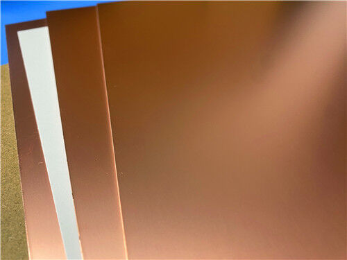
| Brand Name: | Rogers | Model Number: | RO4003C |
|---|
Product Description
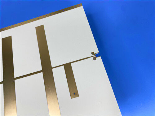
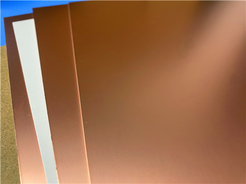
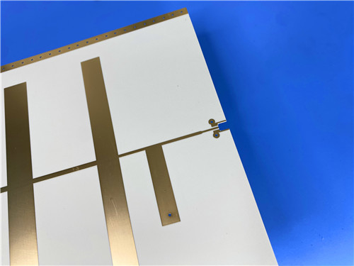
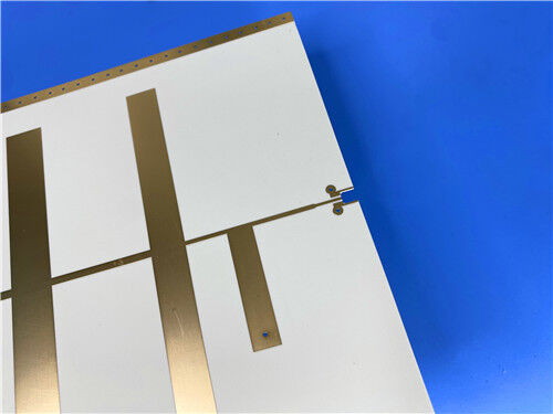
This article presents a custom extra-long Rogers RO4003C high-frequency PCB measuring 1100mm × 350mm—a true long-format board designed for applications that demand continuous high-frequency performance over an extended substrate area. Built on a 0.813mm (32mil) RO4003C laminate with 1oz finished copper, this double-sided board features an immersion gold finish (2u" gold thickness) and is supplied with no solder mask and no silkscreen, delivering an unobstructed, high-integrity copper surface for demanding RF and microwave designs.
RO4003C materials are proprietary woven-glass-reinforced hydrocarbon/ceramic composites that combine the electrical performance of PTFE/woven-glass materials with the manufacturability of epoxy/glass laminates. Available in various configurations, RO4003C laminates utilize 1080 or 1674 glass fabric styles, with all versions meeting the same electrical performance specifications.
RO4003C laminates offer tight control over the dielectric constant (Dk) and low signal loss. They can be processed using the same methods as standard epoxy/glass laminates—but at a fraction of the cost of conventional microwave laminates. Unlike PTFE-based microwave materials, no special through-hole treatments or unique handling procedures are required.
2. Key Specifications
| Parameter | Specification |
| Base Material | Rogers RO4003C |
| Number of Layers | 2 (Double-Sided) |
| Board Dimensions | 1100 mm × 350 mm (1 piece) |
| Substrate Thickness | 0.813 mm (32 mil) |
| Finished Copper Weight | 1 oz (35 μm) |
| Surface Finish | Immersion Gold (2u") |
| Solder Mask | None |
| Silkscreen | None |
| Electrical Testing | 100% prior to shipment |
| Accepted Quality Standard | IPC-Class-2 |
| Artwork Format | Gerber RS-274-X |
| Global Availability | Worldwide shipping |
Features
Benefits
Typical Applications
| RO4003C Typical Value | |||||
| Property | RO4003C | Direction | Units | Condition | Test Method |
| Dielectric Constant,εProcess | 3.38±0.05 | Z | 10 GHz/23℃ | IPC-TM-650 2.5.5.5 Clamped Stripline | |
| Dielectric Constant,εDesign | 3.55 | Z | 8 to 40 GHz | Differential Phase Length Method | |
| Dissipation Factortan,δ | 0.0027 0.0021 |
Z | 10 GHz/23℃ 2.5 GHz/23℃ |
IPC-TM-650 2.5.5.5 | |
| Thermal Coefficient of ε | +40 | Z | ppm/℃ | -50℃to 150℃ | IPC-TM-650 2.5.5.5 |
| Volume Resistivity | 1.7 x 10¹⁰ | MΩ.cm | COND A | IPC-TM-650 2.5.17.1 | |
| Surface Resistivity | 4.2 x 10⁹ | MΩ | COND A | IPC-TM-650 2.5.17.1 | |
| Electrical Strength | 31.2(780) | Z | Kv/mm(v/mil) | 0.51mm(0.020") | IPC-TM-650 2.5.6.2 |
| Tensile Modulus | 19,650(2,850) 19,450(2,821) |
X Y |
MPa(ksi) | RT | ASTM D 638 |
| Tensile Strength | 139(20.2) 100(14.5) |
X Y |
MPa(ksi) | RT | ASTM D 638 |
| Flexural Strength | 276 (40) |
MPa (kpsi) |
IPC-TM-650 2.4.4 | ||
| Dimensional Stability | <0.3 | X,Y | mm/m (mil/inch) |
after etch+E2/150℃ | IPC-TM-650 2.4.39A |
| Coefficient of Thermal Expansion | 11 14 46 |
X Y Z |
ppm/℃ | -55℃to288℃ | IPC-TM-650 2.4.41 |
| Tg | >280 | ℃ TMA | A | IPC-TM-650 2.4.24.3 | |
| Td | 425 | ℃ TGA | ASTM D 3850 | ||
| Thermal Conductivity | 0.71 | W/M/oK | 80℃ | ASTM C518 | |
| Moisture Absorption | 0.06 | % | 48hrs immersion 0.060" sample Temperature 50℃ |
ASTM D 570 | |
| Density | 1.79 | gm/cm3 | 23℃ | ASTM D 792 | |
| Copper Peel Stength | 1.05 (6.0) |
N/mm (pli) |
after solder float 1 oz. EDC Foil |
IPC-TM-650 2.4.8 | |
| Flammability | N/A | UL 94 | |||
| Lead-free Process Compatible | Yes | ||||
Available Configurations
| Parameter | RO4003C Options |
| Standard Thicknesses | 0.008" (0.203mm) ± 0.001"; 0.012" (0.305mm) ± 0.001"; 0.016" (0.406mm) ± 0.0015"; 0.020" (0.508mm) ± 0.0015"; 0.032" (0.813mm) ± 0.002"; 0.060" (1.524mm) ± 0.004" |
| Standard Panel Sizes | 24" × 18" (610 × 457 mm); 24" × 21" (610 × 533 mm); 24" × 36" (610 × 915 mm); 48" × 36" (1219 × 915 mm) |
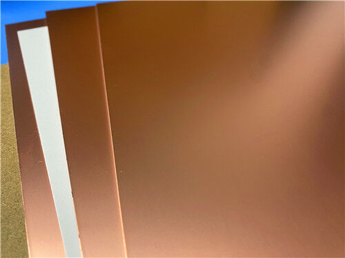
| Standard Claddings | Electrodeposited Copper Foil: ½ oz. (18 μm) HH/HH; 1 oz. (35 μm) H1/H1 |
Low Outgassing Characteristics (Spacecraft Applications)
Rogers laminates, including the RO4000 series, have been tested per NASA's outgassing test procedure SP-R-0022A. The test consists of vacuum heating specimens in a copper enclosure at 125°C for 24 hours with a chrome-plated collector maintained at 25°C. The Total Mass Loss (TML) , Collected Volatile Condensable Materials (CVCM) , and Water Vapor Recovered (WVR) are expressed as a percentage of the original specimen mass.
In general, materials exhibiting a TML of less than 1.0% and CVCM less than 0.1% are considered "low outgassing" and suitable for space applications.
| Product | Total Mass Loss (TML %) | Collected Volatiles (CVCM %) | Water Vapor Recovered (WVR %) |
| RO4003C™ | 0.06 | 0 | 0.02 |
These results confirm that RO4003C laminates meet the low-outgassing requirements for spacecraft applications, making them suitable for spaceborne RF/microwave electronics.
Extra-Long Board Capability
At 1100mm × 350mm, this board is one of the longest RO4003C PCBs available. The extended length makes it ideal for long-strip antenna substrates, phased array antenna elements, and other applications requiring a continuous high-frequency substrate over a large area. Our manufacturing process ensures excellent dimensional stability and uniform electrical performance across the entire board length.
High-Frequency Performance
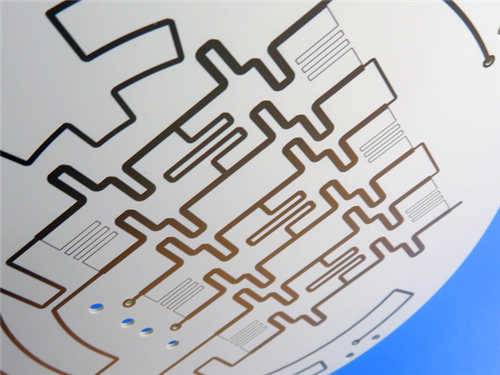
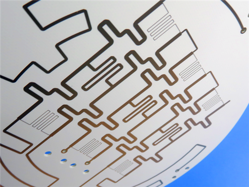
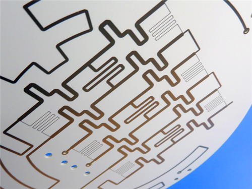
RO4003C's Dk of 3.38 ± 0.05 and Df of 0.0027 at 10 GHz provide exceptional high-frequency performance for RF/microwave circuits, matching networks, and controlled impedance transmission lines. The material's low Z-axis CTE (46 ppm/°C) ensures reliable plated-through-hole quality even in severe thermal shock applications.
Cost-Effective FR-4 Processing
Unlike PTFE-based microwave materials, RO4003C processes like standard FR-4—no special through-hole treatments or handling procedures are required. This significantly reduces fabrication costs while maintaining high-frequency performance, making it ideal for performance-sensitive, high-volume applications.
Immersion Gold (2u") Surface Finish
The immersion gold (2u") surface finish provides a flat, oxidation-resistant, and highly solderable surface with excellent wire-bonding capability. The 2u" gold thickness ensures robust protection against corrosion and wear, making it suitable for long-term reliability in demanding environments.
No Solder Mask / No Silkscreen
The bare copper surface with immersion gold finish provides optimal signal integrity for high-frequency designs. No solder mask or silkscreen minimizes parasitic effects and ensures consistent RF performance across the entire board.
Conclusion
As a specialized supplier of custom high-frequency circuit boards, we combine the proven performance of Rogers RO4003C (Dk 3.38, Df 0.0027, low Z-axis CTE, FR-4 processability, and low outgassing) with our precision manufacturing capabilities to deliver world-class oversized PCB solutions. The 1100mm × 350mm long board offering fully leverages RO4003C's stable dielectric properties, low loss, and dimensional stability, ensuring your most demanding RF, microwave, and antenna applications achieve optimal performance over an extended form factor.
Whether you are developing long-strip antenna substrates, phased array antenna elements, or other large-area high-frequency circuits, our engineering team is ready to support your project. For technical consultations, samples, or volume orders, please contact us today. We look forward to being your trusted partner in high-frequency innovation.
Enter Your Message

RO4350B, 4003C; Rogers 5880, 5870, 6002, 6010, 6006, 6035; RO3003, RO3035, RO3006, RO3010, RO3210,RO3203
TLX-8, TLX-6, TLX-9, TLX-0, TLX-7, TLY-3, TLY-5, RF-35TC, RF-60TC, RF-35A2, RF-60A, AD450, AD600, TMM4, TC350
| Shenzhen Bicheng Electronics Technology Co., Ltd |
| 6-11C Shidai Jingyuan Fuyong Town, Baoan District, Shenzhen City, Guangdong Province, China |
| 86-755-27374946 |
| sales30@bichengpcb.com |