


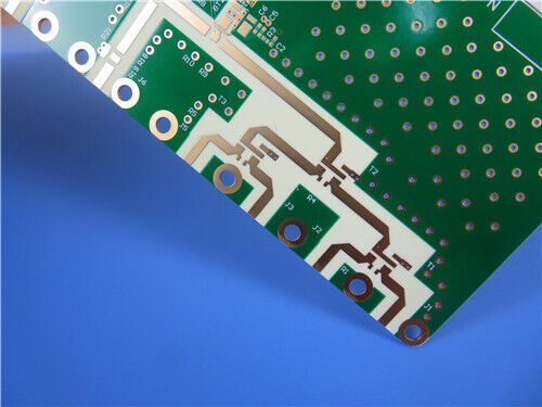
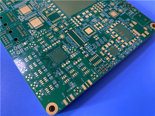
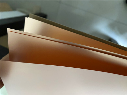

12-Layer High-Speed Digital PCB – TU-872 SLK Low-Loss FR-4 with Via-in-Pad & Impedance Control
Contact Person : Sally Mao
Phone Number : 86-755-27374847
WhatsApp : +8618277967574
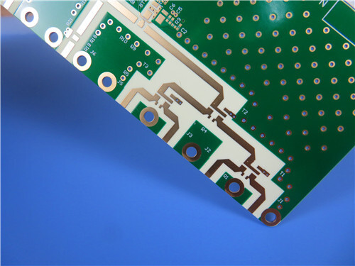
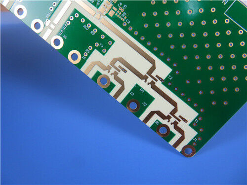
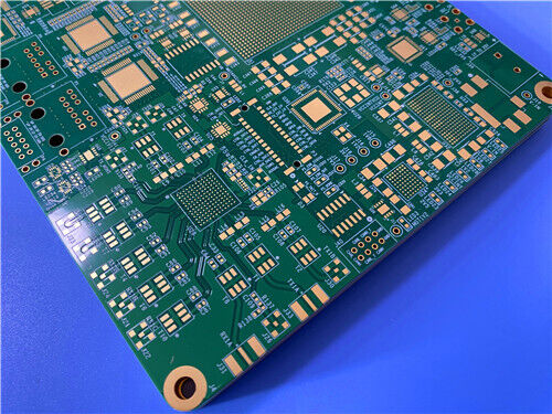
| Brand Name: | Rogers | Model Number: | RO4350B + RO3010 |
|---|
Product Description
What is this hybrid PCB?
It is a 12-layer high-frequency circuit board that combines two complementary Rogers materials: RO4350B (hydrocarbon ceramic, Dk 3.48) and RO3010 (ceramic-filled PTFE, Dk 10.2). This hybrid approach allows designers to optimize different layers for different functions—RO3010 handles high-dielectric-constant antenna layers, while RO4350B provides low-loss RF layers with standard FR-4 processability .
What makes it unique?
The board uses a nickel-free EPIG surface finish (Palladium/Immersion Gold) instead of standard ENIG. This removes the nickel layer's ferromagnetic properties, reducing insertion loss above 24 GHz—critical for 77 GHz automotive radar and satellite communications .
Key Takeaways
| For Designers | For Procurement Professionals |
| ✅ RO3010 (Dk 10.2) – High Dk for compact antenna layers | ✅ FR-4 compatible processing – RO4350B uses standard workflows |
| ✅ RO4350B (Dk 3.48) – Low-loss RF layers, UL94 V-0 rated | ✅ Lower cost – Hybrid approach saves vs. all-RO3010 stacks |
| ✅ Nickel-free EPIG – 0.18 dB/in lower loss than ENIG above 24 GHz | ✅ RO4450F prepreg – CTE-matched for reliable lamination |
| ✅ Blind vias – 7 groups (1-2, 2-5, 2-6, 2-8, 1-9, 10-12, 3-12) | ✅ V-0 rated – RO4350B and RO4450F are UL94 V-0 |
| ✅ CTE matched to copper – 10-17 ppm/°C, excellent dimensional stability | ✅ Worldwide availability – Rogers materials are globally sourced |
| ✅ 3.14 mm thickness – Rigid, high-layer-count construction | ✅ Lead-free compatible – Supports 260°C reflow |
1. Why a Hybrid Stackup?
When a PCB is built on dissimilar materials instead of one material throughout, it is called a hybrid PCB . This approach allows designers to partition electrical functions by material characteristics rather than forcing a single material to do everything.
In this design:
RO3010 handles the high-Dk antenna layers (Dk 10.2) – The high dielectric constant allows for compact patch antenna arrays and smaller circuit footprints .
RO4350B forms the intermediate RF layers (Dk 3.48) – It provides low-loss performance with standard FR-4 processability .
RO4450F prepreg bonds everything together – This dual-compatible resin system ensures reliable lamination between PTFE-based RO3010 and hydrocarbon-based RO4350B .
2. Material Overview
RO4350B – The Workhorse of the RO4000 Series
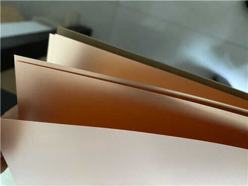
RO4350B is a hydrocarbon ceramic laminate designed for superior high-frequency performance with low-cost circuit fabrication. It can be fabricated using standard FR-4 processes—unlike PTFE materials that require sodium etch treatment .
| Property | Value |
| Dielectric Constant (process) | 3.48 ± 0.05 at 10 GHz |
| Design Dk | 3.66 (8-40 GHz) |
| Dissipation Factor | 0.0037 at 10 GHz |
| TCDk | +50 ppm/°C |
| CTE X/Y | 10/12 ppm/°C |
| CTE Z | 32 ppm/°C |
| Tg | >280°C |
| Td | 390°C |
| UL Flammability | V-0 |
| Thermal Conductivity | 0.69 W/m·K |
| Moisture Absorption | 0.06% |
RO4350B is the go-to material for cost-sensitive RF designs that still need controlled impedance and low insertion loss . It is UL94 V-0 rated and fully compatible with lead-free processing.
RO3010 – High-DK PTFE-Ceramic Material
RO3010 is a ceramic-filled PTFE composite with a high dielectric constant of 10.2. It is designed for applications that require compact circuit footprints .
| Property | Value |
| Dielectric Constant (process) | 10.2 ± 0.30 at 10 GHz |
| Design Dk | 11.20 (8-40 GHz) |
| Dissipation Factor | 0.0022 at 10 GHz |
| TCDk | -395 ppm/°C |
| CTE X/Y | 13/11 ppm/°C |
| CTE Z | 16 ppm/°C |
| Td | 500°C |
| UL Flammability | V-0 |
| Thermal Conductivity | 0.95 W/m·K |
| Moisture Absorption | 0.05% |
RO3010's high Dk allows significantly smaller circuit footprints—useful for compact couplers, filters, and phased-array feed networks where board real estate is tight . It is not a general-purpose material but is the right tool for miniaturization-driven designs.
RO4450F Prepreg
RO4450F is a halogen-free, high-Tg prepreg used in multilayer constructions to bond Rogers cores together or to bond Rogers layers to FR-4 in hybrid stackups . It is UL94 V-0 rated and ensures reliable lamination between different material families.
3. Complete PCB Specifications
| Specification | Detail |
| Board Type | 12-Layer Hybrid RF/Microwave PCB |
| Base Materials | RO4350B (top/bottom) + RO3010 (intermediate layers) + RO4450F Prepreg |
| Finished Board Thickness | 3.14 mm |
| Board Dimensions | 107 × 91.5 mm (2 pieces) |
| Finished Copper (Outer) | 1 oz (35 µm) |
| Finished Copper (Inner) | 0.5 oz (18 µm) |
| Surface Finish | EPIG (Nickel-free Electroless Palladium/Immersion Gold) |
| Top Solder Mask | Green |
| Bottom Solder Mask | Green |
| Top Silkscreen | White |
| Bottom Silkscreen | White |
| Blind Vias | 1-2, 2-5, 2-6, 2-8, 1-9, 10-12, 3-12 |
| IPC Classification | Class 2 |
| Artwork Format | Gerber RS-274-X |
| Testing | 100% Electrical Test (before shipment) |
Hybrid Construction Benefits
The pairing of RO3010 and RO4350B is enabled by RO4450F's dual-compatibility resin system. The CTE of RO3010 (13/11 ppm/°C) and RO4350B (10/12 ppm/°C) are closely matched to standard copper foil, delivering post-etch dimensional shrinkage below 0.35 mm/m . Unlike full PTFE RO3000 multilayer boards, RO4350B intermediate layers use standard FR-4 workflows without sodium etch via treatment, cutting manufacturing cycle time by 30% and lowering total material cost by 22% versus all-RO3010 12-layer stacks .
Nickel-Free EPIG Finish Advantages
Conventional ENIG finish incorporates an electroless nickel barrier layer with ferromagnetic properties that introduce significant insertion loss above 24 GHz . This product's nickel-free EPIG deposits a thin palladium barrier directly onto copper, removing nickel-related RF attenuation. Comparative testing at 10–40 GHz demonstrates 0.18 dB/in lower insertion loss versus standard ENIG . This is critical for 77 GHz automotive radar and satellite communications.
The thin palladium-gold stack also minimizes conductor geometry buildup, supporting tight line-space HDI blind via routing without short-circuit risk .
Blind Via HDI Design
Seven groups of staggered blind vias eliminate long through-via stubs that create parasitic capacitance and inductance at millimeter-wave bands . Multi-stage blind via stacking separates top antenna layer interconnections from inner power/ground transitions, reducing RF signal path length by 40% compared to conventional through-via 12-layer boards .
Electrical & Thermal Stability
RO3010 features a Dk thermal coefficient of -395 ppm/°C while RO4350B delivers +50 ppm/°C Dk drift from -50°C to 150°C; the hybrid stackup's composite dielectric temperature response balances antenna resonant frequency drift and broadband transmission line impedance stability across automotive-grade operating ranges (-40°C to 125°C) . RO3010 thermal conductivity (0.95 W/m·K) provides superior heat dissipation for high-gain antenna patches, while RO4350B's 0.69 W/m·K thermal conductivity spreads power amplifier heat across inner ground planes .
Application Fields
Q1: Why use a hybrid stackup instead of a single material?
A hybrid stackup partitions electrical functions by material characteristics. RO3010's high Dk (10.2) is used for compact antenna layers and miniaturized feed networks. RO4350B (3.48) provides low-loss RF layers with FR-4 processability, reducing cost. RO4450F prepreg bonds them reliably . The approach saves approximately 22% cost compared to an all-RO3010 12-layer board .
Q2: What is nickel-free EPIG finish and why does it matter?
EPIG (Electroless Palladium/Immersion Gold) replaces the nickel layer in standard ENIG with a thin palladium barrier. Nickel is ferromagnetic and introduces insertion loss above 24 GHz . The nickel-free finish delivers 0.18 dB/in lower loss than ENIG at 10–40 GHz while maintaining solder joint reliability and gold wire bond capability .
Q3: Are RO4350B and RO3010 UL94 V-0 rated?
Yes. RO4350B is UL94 V-0 rated . RO3010 is also V-0 rated . Note that RO4003C is not UL94 V-0 rated—if V-0 is a requirement, RO4350B is the correct choice .
Q4: How are RO4350B and RO3010 bonded together?
They are bonded using RO4450F prepreg, a halogen-free, high-Tg bonding material with dual-compatibility resin. RO4450F is designed specifically for multilayer constructions bonding Rogers cores together or bonding Rogers layers to FR-4 . It is UL94 V-0 rated and ensures CTE-matched lamination without thermal reliability issues .
Q5: What applications are blind vias used for in this design?
Seven groups of staggered blind vias (1-2, 2-5, 2-6, 2-8, 1-9, 10-12, 3-12) eliminate long through-via stubs that create parasitic capacitance and inductance at millimeter-wave bands. They reduce RF signal path length by 40% compared to conventional through-via 12-layer boards, improving filter stopband attenuation and antenna radiation efficiency .
Ready to Get Started?
This 12-layer RO4350B+RO3010 hybrid PCB can be manufactured with nickel-free EPIG finish and blind via structures.
Contact us today for:
Hybrid stackup design assistance
Material selection guidance (RO4350B, RO3010, RO4450F)
Impedance calculation and design support
PCB quoting and DFM review
Technical support for your specific application
Enter Your Message

RO4350B, 4003C; Rogers 5880, 5870, 6002, 6010, 6006, 6035; RO3003, RO3035, RO3006, RO3010, RO3210,RO3203
TLX-8, TLX-6, TLX-9, TLX-0, TLX-7, TLY-3, TLY-5, RF-35TC, RF-60TC, RF-35A2, RF-60A, AD450, AD600, TMM4, TC350
| Shenzhen Bicheng Electronics Technology Co., Ltd |
| 6-11C Shidai Jingyuan Fuyong Town, Baoan District, Shenzhen City, Guangdong Province, China |
| 86-755-27374946 |
| sales30@bichengpcb.com |