



Wangling TFA1020 double sided PCB material Aerospace-Grade PTFE/Ceramic Composite Laminate with RTF (Reverse-Treated Foil)
Contact Person : Sally Mao
Phone Number : 86-755-27374847
WhatsApp : +8618277967574
| Brand Name: | Rogers | Model Number: | TF960 |
|---|
Product Description
TF960 High-DK Ceramic-Filled PTFE Laminate & Custom 2-Layer PCB Solution
1. Introduction to TF960 High-Frequency Laminate
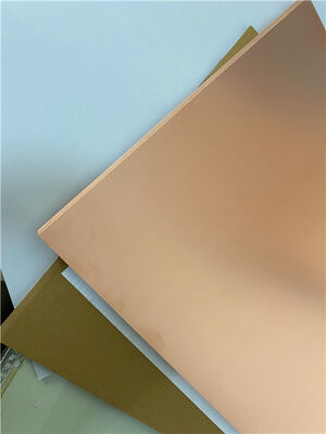
TF960 is a high-performance ceramic-filled PTFE composite laminate manufactured by Taizhou Wangling Insulation Material Factory. Unlike traditional PTFE fiberglass laminates, TF960 is composed of microwave-grade PTFE resin combined with ceramic fillers, without any fiberglass cloth reinforcement. This unique composition allows for precise dielectric constant adjustment by varying the ceramic-to-PTFE ratio, resulting in exceptional electrical performance and high reliability.
TF960 specifically features a dielectric constant of 9.6 ± 0.19 at 10 GHz, making it an ideal choice for high-frequency impedance matching, miniaturization, and phase-sensitive applications. The material contains no fiberglass reinforcement, which eliminates glass-fiber-induced anisotropy and provides superior electrical performance compared to woven-reinforced PTFE materials.
The material supports lead-free assembly (compatible with 260°C reflow processes) and offers excellent thermal stability, moisture resistance, and low outgassing, making it suitable for aerospace, defense, and high-reliability commercial applications.
2. Key Technical Specifications (TF960)
| Property | Test Condition | Unit | TF960 Value |
| Dielectric Constant @ 10 GHz | 10 GHz | — | 9.6 ± 0.19 |
| Dielectric Constant Tolerance | — | — | ±2% |
| Dissipation Factor @ 10 GHz | 10 GHz | — | 0.0012 |
| Thermal Coefficient of Dk | -55°C to +150°C | ppm/°C | -260 |
| Peel Strength (1 oz, Normal) | 1 oz, Normal State | N/mm | >0.6 |
| Peel Strength (1 oz, After Damp Heat) | 1 oz, After Damp Heat | N/mm | >0.4 |
| Volume Resistivity | Normal State, 500V | MΩ·cm | >1×10⁹ |
| Surface Resistivity | Normal State, 500V | MΩ | >1×10⁷ |
| CTE – X axis | -55°C to +150°C | ppm/°C | 50 |
| CTE – Y axis | -55°C to +150°C | ppm/°C | 50 |
| CTE – Z axis | -55°C to +150°C | ppm/°C | 65 |
| Moisture Absorption | 20±2°C, 24 hours | % | ≤0.05 |
| Density | Room Temperature | g/cm³ | 3.02 |
| Thermal Conductivity | Z-direction | W/(m·K) | 0.68 |
| Long-Term Operating Temperature | — | °C | -80 to +200 |
| Flammability | — | UL-94 | V-0 |
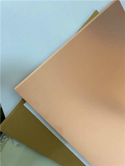
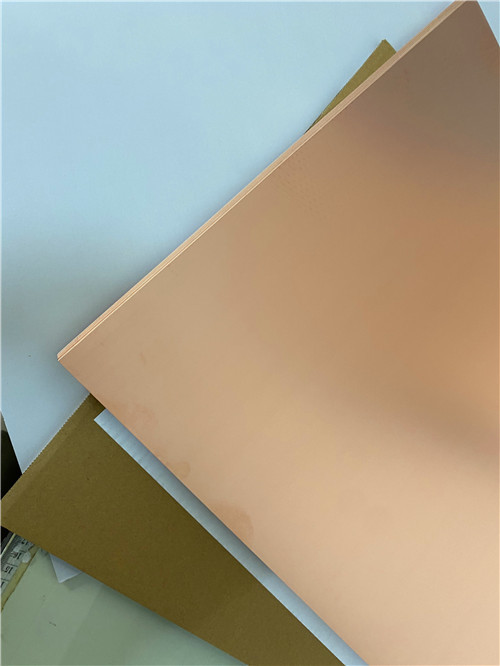
| Material Composition | — | — | PTFE + Ceramic Fillers + ED Copper Foil |
Available copper foil: ED copper, 0.018 mm and 0.035 mm thicknesses.
Standard panel sizes: 150×150 mm, 250×250 mm.
3. Features & Benefits
TF960 delivers a comprehensive set of advantages for high-frequency and high-reliability applications:
| Feature | Description |
| High Dielectric Constant (9.6) | Enables circuit miniaturization and reduced wavelength |
| Tight Dk Tolerance (±0.19 / ±2%) | Excellent batch-to-batch consistency |
| Ultra-Low Dissipation Factor | 0.0012 @ 10 GHz – minimizes insertion loss |
| No Glass Fiber Reinforcement | Eliminates anisotropy and reduces dielectric loss |
| Wide Operating Temperature Range | -80°C to +200°C – exceeds standard PTFE materials |
| Radiation Resistance & Low Outgassing | Suitable for space and aerospace applications |
| UL 94 V-0 Flammability | Meets stringent safety requirements |
| Lead-Free Assembly Compatible | Supports 260°C reflow processes |
Superior Electrical Performance: The absence of fiberglass cloth eliminates the "glass-fiber effect" that can cause variations in dielectric constant and increased loss at high frequencies. The ceramic-filled PTFE composition provides stable, isotropic electrical properties.
Circuit Miniaturization: The high Dk of 9.6 allows for significant reduction in circuit size compared to low-Dk materials, enabling compact RF and microwave designs.
Excellent Temperature Stability: With a TCDk of -260 ppm/°C, TF960 maintains stable electrical performance across a wide temperature range.
Low Moisture Absorption (≤0.05%): Ensures consistent dielectric properties in humid environments.
Enhanced Thermal Management: Thermal conductivity of 0.68 W/(m·K) supports efficient heat dissipation in power applications.
Easy Processing: Can be processed using standard thermoplastic PCB manufacturing techniques – no specialized processing required.
High Reliability: Excellent dimensional stability with low CTE (50/50/65 ppm/°C) ensures reliable plated-through-hole integrity.
4. Custom 2-Layer PCB Solution on TF960
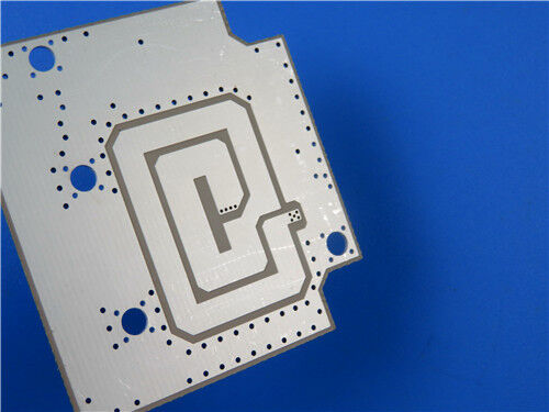
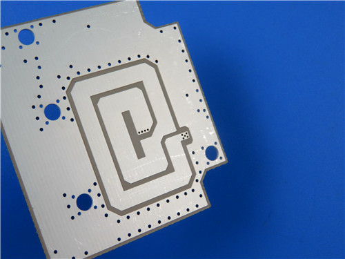
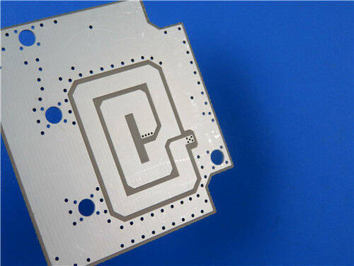
Leveraging the advanced properties of TF960, we offer the following precision-engineered 2-layer rigid PCB solution. This design is ideal for high-frequency, high-DK applications requiring circuit miniaturization and excellent signal integrity.
PCB Construction Details
| Parameter | Specification |
| Base Material | Wangling TF960 (ED Copper) |
| Number of Layers | 2 |
| Finished Board Size | 102 mm × 86 mm (±0.15 mm) |
| Finished Board Thickness | 0.7 mm |
| Minimum Trace / Space | 5 / 8 mils |
| Minimum Hole Size | 0.25 mm (through-hole only; no blind vias) |
| Outer Layer Copper Weight | 1 oz (35 μm) |
| Via Plating Thickness | 20 μm |
| Surface Finish | Immersion Silver |
| Top Silkscreen | White |
| Bottom Silkscreen | None |
| Top Solder Mask | Blue |
| Bottom Solder Mask | None |
| Electrical Testing | 100% prior to shipment |
| Accepted Quality Standard | IPC-Class-2 |
| Artwork Format | Gerber RS-274-X |
| Global Availability | Worldwide shipping |
Design & Manufacturing Highlights
High-DK Design: With a Dk of 9.6 ± 0.19, this PCB enables significant circuit size reduction and is ideal for compact RF and microwave modules requiring precise impedance control.
Ultra-Low Loss Performance: The dissipation factor of 0.0012 at 10 GHz ensures minimal insertion loss, preserving signal integrity in high-frequency applications.
Fine-Feature Capability: Supports 5/8 mil trace/space and 0.25 mm micro-vias, enabling dense high-frequency circuit layouts.
Blue Solder Mask on Top: The blue solder mask provides protection for the top copper layer while allowing visual inspection and enhancing the visual identification of the PCB.
Immersion Silver Surface Finish: Provides a flat, highly conductive, and oxidation-resistant surface with excellent solderability. Immersion silver is particularly well-suited for high-frequency applications due to its excellent electrical conductivity and low skin-effect losses.
Reliable PTH Interconnects: With 20 μm via plating and controlled CTE, the PCB offers reliable plated-through-hole integrity.
Strict Quality Control: Every board undergoes 100% electrical testing and is manufactured to IPC-Class-2 standards, guaranteeing consistent quality and performance.
5. Typical Applications
Microwave & RF Transceivers
5G/6G Massive MIMO Antennas
Radar Systems
Satellite Communication Payloads
High-Power RF Amplifiers
Test & Measurement Equipment
Phase Shifters & Beamforming Networks
Filters & Couplers
6. Conclusion
As a specialized supplier of custom high-frequency circuit boards, we combine the proven performance of Wangling TF960 – a high-DK, ceramic-filled PTFE laminate with exceptional electrical properties and reliability – with our precision manufacturing capabilities to deliver world-class PCB solutions. Our 2-layer offering fully leverages TF960's high dielectric constant (9.6), ultra-low loss (0.0012 @ 10 GHz), excellent thermal stability, and radiation resistance, ensuring your most demanding RF, microwave, and aerospace designs achieve optimal performance and reliability.
Whether you are developing 5G/6G antenna systems, automotive radar, satellite communication payloads, or high-power RF amplifiers, our engineering team is ready to support your project. For technical consultations, samples, or volume orders, please contact us today. We look forward to being your trusted partner in high-frequency innovation.
Enter Your Message

RO4350B, 4003C; Rogers 5880, 5870, 6002, 6010, 6006, 6035; RO3003, RO3035, RO3006, RO3010, RO3210,RO3203
TLX-8, TLX-6, TLX-9, TLX-0, TLX-7, TLY-3, TLY-5, RF-35TC, RF-60TC, RF-35A2, RF-60A, AD450, AD600, TMM4, TC350
| Shenzhen Bicheng Electronics Technology Co., Ltd |
| 6-11C Shidai Jingyuan Fuyong Town, Baoan District, Shenzhen City, Guangdong Province, China |
| 86-755-27374946 |
| sales30@bichengpcb.com |