


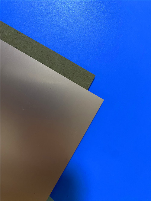

Custom PCB – 4-Layer RO4003C + RO4450F Hybrid with Via-in-Pad & Immersion Gold 2u"
Contact Person : Sally Mao
Phone Number : 86-755-27374847
WhatsApp : +8618277967574
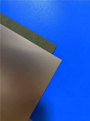
| Brand Name: | Rogers | Model Number: | CLTE-MW |
|---|
Product Description
As 5G and millimeter-wave systems push toward higher frequencies, the spacing between signal and ground becomes a critical design parameter—often demanding dielectric thicknesses of only a few mils. The CLTE-MW laminate from Rogers Corporation is engineered specifically for these thickness-constrained applications, offering a high-performance, cost-effective material available in seven thickness options from 3 to 10 mils.
CLTE-MW laminates are reinforced with spread glass which, along with a high filler loading, helps minimize the high-frequency glass weave effects on electromagnetic wave propagation. This unique construction ensures that ideal signal-to-ground spacing exists for 5G and other millimeter-wave applications, while maintaining low loss and excellent plated through-hole reliability.
Key Properties at a Glance (CLTE-MW):
| Property | Typical Value | Test Condition |
| Loss Tangent | 0.0015 | 10 GHz |
| Z-Axis CTE | 30 ppm/°C | — |
| Thermal Conductivity | 0.42 W/(m·K) | — |
| Flammability Rating | UL 94 V-0 | — |
| Available Thicknesses | 3 to 10 mils (7 options) | — |
CLTE Series Overview
The broader CLTE™ laminate family has proven excellent dimensional stability and low planar CTE, providing consistent performance for embedded resistors—among the lowest variance available for PTFE-based laminates. CLTE laminates have a long history of use with Resistor Foil and are available with a full range of cladding types, including electrodeposited, reverse treated copper, rolled copper foil, and more.
Key Properties at a Glance (CLTE):
| Property | Typical Value | Test Condition |
| Dielectric Constant (process) | 2.98 | 10 GHz |
| Dissipation Factor | 0.0021 | 10 GHz |
| Thermal Coefficient of Dk | 6 ppm/°C | -50 to 150°C |
| CTE - X / Y / Z | 9.9 / 9.4 / 57.9 ppm/°C | -55 to 288°C |
| Thermal Conductivity | 0.5 W/(m·K) | Z-direction |
| Decomposition Temperature (Td) | 538°C | TGA |
| Moisture Absorption | 0.04% | — |
| Density | 2.31 g/cm³ | — |
| Flammability Rating | UL 94 V-0 | — |
The CLTE series offers a low Z-axis CTE of 20 ppm/°C for high plated through-hole reliability, dielectric constant stability with temperature change, and reduced stress attachment to ceramic active devices. It is available with heavy metal backing (aluminum, brass, and copper) and can be reliably designed with embedded resistor networks.
Applications
CLTE-MW and the CLTE series are engineered for demanding high-frequency applications, with typical applications including:
Custom PCB Manufacturing on CLTE-MW
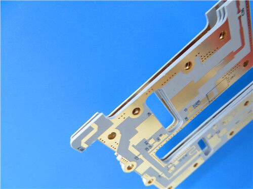
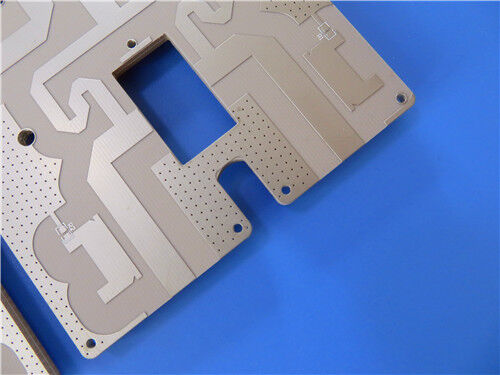
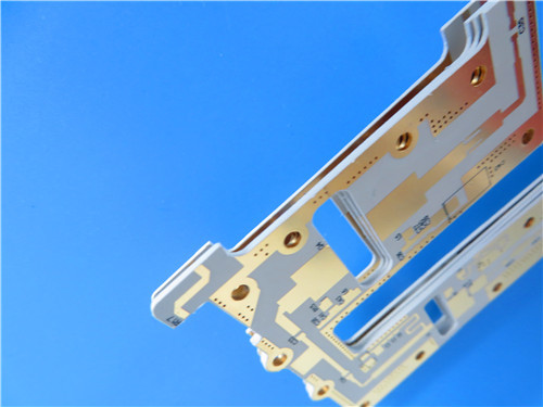
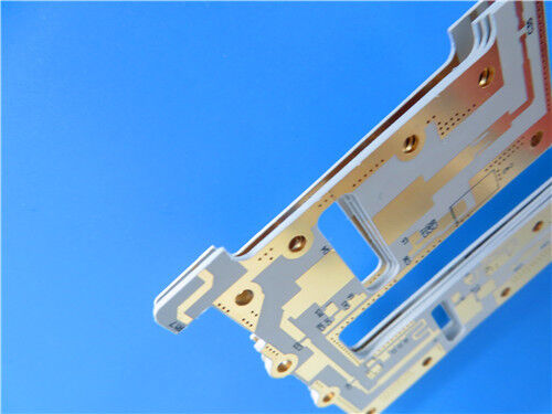
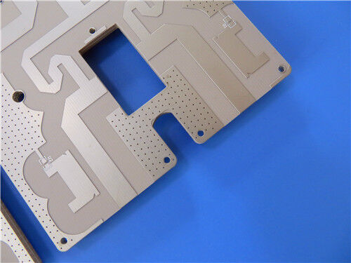
As a specialized manufacturer of high-frequency printed circuit boards, we offer comprehensive fabrication services using Rogers CLTE-MW and other advanced materials. The following specification details a representative 2-layer ultra-thin implementation:
PCB Construction Details:
| Parameter | Specification |
| Base Material | CLTE-MW |
| Layer Count | 2-layer rigid |
| Board Dimensions | 35.8mm × 66.5mm per panel, ±0.15mm |
| Finished Thickness | 0.2mm |
| Copper Weight | 1 oz (1.4 mils) outer layers |
| Minimum Trace/Space | 4 / 6 mils |
| Minimum Hole Size | 0.3mm |
| Via Structure | No blind or buried vias |
| Via Plating Thickness | 20 μm |
| Surface Finish | Pure Gold |
| Solder Mask | Green, top side only |
| Silkscreen | White, top side only |
| Electrical Test | 100% prior to shipment |
| Artwork Format | Gerber RS-274-X |
| Quality Standard | IPC-Class-2 |
Seven Thickness Options for Design Flexibility:
CLTE-MW is available in seven thickness options from 3 to 10 mils, ensuring that ideal signal-to-ground spacing exists for 5G and other millimeter-wave applications. This flexibility allows designers to optimize transmission line impedance and propagation characteristics without compromising on electrical performance.
Spread Glass Reinforcement:
The spread glass reinforcement, combined with high filler loading, helps minimize high-frequency glass weave effects on electromagnetic wave propagation. This reduces impedance variations and skew, which is particularly important in high-speed and high-frequency circuits.
Low Loss Tangent:
A loss tangent of 0.0015 at 10 GHz enables low-loss designs for millimeter-wave applications, supporting efficient signal transmission in 5G and satellite communication systems.
Excellent Plated Through-Hole Reliability:
The low Z-axis CTE of 30 ppm/°C provides excellent plated through-hole reliability, even in the ultra-thin constructions enabled by CLTE-MW.
Good Heat Dissipation:
With a thermal conductivity of 0.42 W/(m·K), CLTE-MW provides good heat dissipation in aggressive designs, supporting reliable operation in thermally challenging environments.
Ultra-Thin Construction Capability:
The 0.2mm finished thickness demonstrated here (0.102mm core + 2× 35μm copper) showcases the material's suitability for applications with severe thickness limitations due to physical or electrical constraints. This makes CLTE-MW ideal for compact, lightweight RF systems.
Pure Gold Surface Finish:
The pure gold surface finish provides excellent conductivity, corrosion resistance, and wire-bonding capability, essential for high-reliability RF and microwave circuits.
Quality and Availability
All boards are manufactured in compliance with IPC-Class-2 quality standards, ensuring robust reliability for commercial, industrial, and defense-related applications. 100% electrical testing is performed prior to shipment to guarantee functional integrity.
Our production capability extends to worldwide availability, with flexible shipping and logistics support for both prototype and volume requirements. We offer rapid turnaround and competitive pricing while maintaining strict process control.
For inquiries about custom stack-ups, alternative thicknesses within the CLTE-MW range (3 to 10 mils), CLTE series configurations, heavy metal backing (aluminum, brass, copper), embedded resistor networks, or other requirements, please contact our sales engineering team—we are ready to support your high-frequency circuit board requirements.
Enter Your Message

RO4350B, 4003C; Rogers 5880, 5870, 6002, 6010, 6006, 6035; RO3003, RO3035, RO3006, RO3010, RO3210,RO3203
TLX-8, TLX-6, TLX-9, TLX-0, TLX-7, TLY-3, TLY-5, RF-35TC, RF-60TC, RF-35A2, RF-60A, AD450, AD600, TMM4, TC350
| Shenzhen Bicheng Electronics Technology Co., Ltd |
| 6-11C Shidai Jingyuan Fuyong Town, Baoan District, Shenzhen City, Guangdong Province, China |
| 86-755-27374946 |
| sales30@bichengpcb.com |