



Custom PCB – 4-Layer RO4003C + RO4450F Hybrid with Via-in-Pad & Immersion Gold 2u"
Contact Person : Sally Mao
Phone Number : 86-755-27374847
WhatsApp : +8618277967574
| Brand Name: | Isola | Model Number: | MT40 |
|---|
Product Description
1. Material Overview – I-Tera® MT40 (Isola)
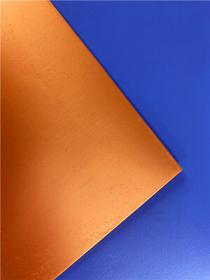
I-Tera® MT40 is a very low-loss, high-performance modified epoxy/FR-4 resin system from Isola Group, reinforced with E-glass woven fabric. It is specifically engineered for high-speed digital and RF/microwave printed circuit designs where standard FR-4 falls short but PTFE or hydrocarbon materials are cost-prohibitive or difficult to process .
Key Material Characteristics
| Feature | Benefit |
| Dk = 3.45 (stable ±0.05) | Low and stable dielectric constant from 2–10 GHz – consistent impedance across frequency . |
| Df = 0.0031 | Very low dissipation factor – minimizes insertion loss for high-speed serial links and RF front-ends . |
| Tg (DSC) = 215°C / DMA = 230°C | High thermal stability – supports lead-free assembly and 260°C peak reflow . |
| Td = 360°C | Excellent thermal decomposition resistance – robust for harsh operating environments . |
| Stable Dk from -55°C to +125°C | Consistent electrical performance across temperature extremes – essential for outdoor and automotive applications . |
| FR-4 process compatible | No sodium etch or plasma desmear required – standard FR-4 fabrication lines . |
| CAF resistant | Prevents conductive anodic filament formation – critical for high-voltage, fine-pitch designs . |
| Multiple reflow capable | Withstands multiple lamination cycles – supports HDI and sequential lamination . |
| RoHS compliant | Meets environmental regulations . |
2. Material Datasheet – Consolidated Properties (I-Tera MT40)
| I-Tera® MT40 | ||||
| Property | Typical Value | Units | Test Method | |
| Metric (English) | IPC-TM-650 (or as noted) | |||
| Glass Transition Temperature (Tg) by DSC | 215 | °C | 2.4.25C | |
| Glass Transition Temperature (Tg) by DMA | 230 | °C | 2.4.24.4 | |
| Glass Transition Temperature (Tg) by TMA | 210 | °C | 2.4.24C | |
| Decomposition Temperature (Td) by TGA @ 5% weight loss | 360 | °C | 2.4.24.6 | |
| Time to Delaminate by TMA (Copper removed) | A. T260 | >60 | Minutes | 2.4.24.1 |
| B. T288 | ||||
| Z-Axis CTE | A. Pre-Tg | 55 | ppm/°C | 2.4.24C |
| B. Post-Tg | 290 | ppm/°C | ||
| C. 50 to 260°C, (Total Expansion) | 2.8 | % | ||
| X/Y-Axis CTE | Pre-Tg | 12 | ppm/°C | 2.4.24C |
| Thermal Conductivity | 0.61 | W/m·K | ASTM E1952 | |
| Thermal Stress 10 sec @ 288ºC (550.4ºF) | A. Unetched | Pass | Pass Visual | 2.4.13.1 |
| B. Etched | ||||
| Dk, Permittivity | A. @ 2 GHz | 3.45 | — | 2.5.5.5 |
| B. @ 5 GHz | ||||
| C. @ 10 GHz | ||||
| Df, Loss Tangent | A. @ 2 GHz | 0.0031 | — | Bereskin Stripline |
| B. @ 5 GHz | ||||
| C. @ 10 GHz | ||||
| Volume Resistivity | C-96/35/90 | 1.33 x 10^7 | MΩ-cm | 2.5.17.1 |
| Surface Resistivity | C-96/35/90 | 1.33 x 10^5 | MΩ | 2.5.17.1 |
| Dielectric Breakdown | 45.4 | kV | 2.5.6B | |
| Arc Resistance | 139 | Seconds | 2.5.1B | |
| Electric Strength (Laminate & laminated prepreg) | 45 (1133) | kV/mm (V/mil) | 2.5.6.2A | |
| Comparative Tracking Index (CTI) | 3 | Class (Volts) | UL 746A | |
| ASTM D3638 | ||||
| Peel Strength | 1 oz. EDC foil | 1.0 (5.7) | N/mm (lb/inch) | 2.4.8C |
| Flexural Strength | A. Length direction | 490 (71.0) | MPa (kpsi) | 2.4.4B |
| B. Cross direction | 400 (58.0) | |||
| Tensile Strength | A. Length direction | 269 (39.0) | MPa (kpsi) | ASTM D3039 |
| B. Cross direction | 241 (35.0) | |||
| Young's Modulus | A. Length direction | 3060 | ksi | ASTM D790-15e2 |
| B. Cross direction | 2784 | |||
| Poisson's Ratio | A. Length direction | 0.234 | — | ASTM D3039 |
| B. Cross direction | 0.222 | |||
| Moisture Absorption | 0.1 | % | 2.6.2.1A | |
| Flammability (Laminate & laminated prepreg) | V-0 | Rating | UL 94 | |
| Relative Thermal Index (RTI) | 130 | °C | UL 796 | |
Note: Dk/Df values are stable from -55°C to +125°C up to W-band frequencies (75–110 GHz) .
Standard Availability
| Parameter | Options |
| Standard Laminate Thickness | 10, 20, 30, 60 mil (0.25, 0.51, 0.76, 1.5 mm) – 0.254mm (10 mil) used here |
| Copper Foil Type | HVLP (VLP2) ≤2.5 µm Rz JIS, RTF (Reverse Treat Foil), HTE Grade 3, Embedded resistor foil |
| Copper Weight | ½ oz, 1 oz, 2 oz (18, 35, 70 µm) – 1 oz used here |
| Glass Fabric | E-glass, Square weave glass, Mechanically spread glass |
| Prepreg | Available with tooling panels, moisture barrier packaging |
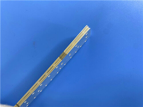
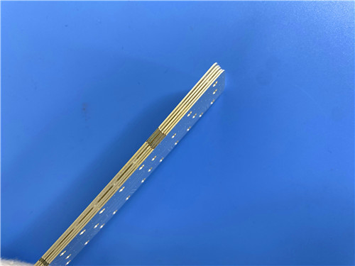
3. Custom PCB – Double-Layer I-Tera MT40 with Castellated Edges
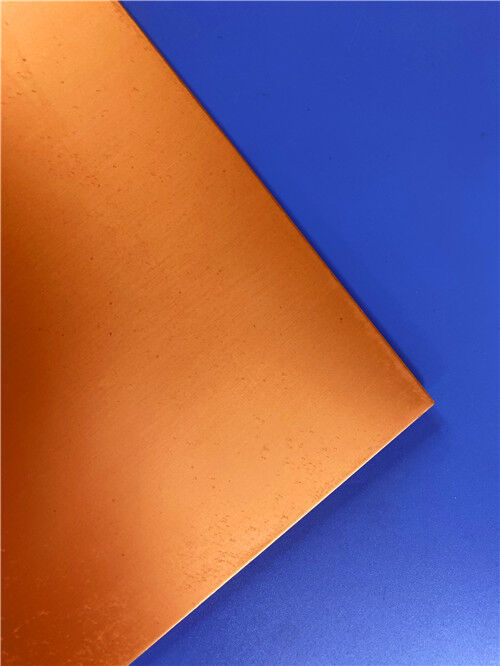
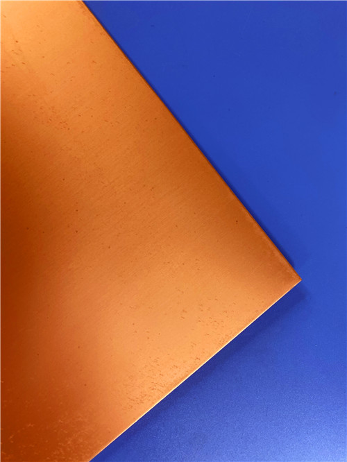
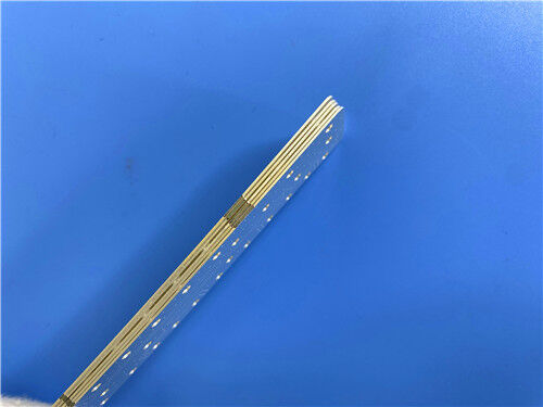
This double-layer board demonstrates our capability to handle high-frequency material processing, HVLP copper foil selection, and castellated edge fabrication for module applications.
Basic Specifications
| Item | Specification |
| Layer Count | 2 layers |
| Base Material | Isola I-Tera MT40 – 0.254mm (10 mil) laminate |
| Finished Copper Weight | 1 oz / 1 oz (both top and bottom) |
| Copper Foil Type | HVLP (VLP2) – ≤2.5 µm Rz JIS for low conductor loss |
| Surface Finish | Immersion Silver – excellent for RF applications, low contact resistance |
| Solder Mask | Green (both sides) |
| Silkscreen (Top) | White, oil-free – clean, no contamination risk |
| Silkscreen (Bottom) | None, oil-free – bare surface for optimal soldering |
| Panel Size | 108mm × 35mm (1 piece) |
Castellated Edges (Plated Edges)
Castellated holes are plated half-holes along the board edge, designed for solder-down module connections. They provide a visible solder fillet that can be inspected optically – a significant quality advantage over LGA (land grid array) connections .
HDI and Sequential Lamination Capability
I-Tera MT40 supports HDI microvia construction and sequential lamination processes. Its dimensional stability under multiple press cycles – a direct benefit of its glass-reinforced architecture versus PTFE – makes it more predictable in production than PTFE alternatives .
4. Why I-Tera MT40 for This Design?
| Requirement | How I-Tera MT40 Addresses It |
| RF/microwave signal integrity | Df = 0.0031 minimizes insertion loss – critical for RF front-end modules |
| Temperature-stable performance | Dk stable from -55°C to +125°C up to W-band – essential for outdoor/automotive |
| Cost-effective alternative to PTFE | FR-4 process compatible – no sodium etch or plasma desmear required |
| Low conductor loss | HVLP copper foil (≤2.5 µm Rz) – reduces roughness-induced loss |
| Edge-mount module design | Castellated edges enable reliable solder-down connection |
| Multiple reflow capability | Supports sequential lamination and multiple assembly cycles |
| CAF resistance | Prevents conductive anodic filament formation – long-term reliability |
Application Areas
Q1: What makes I-Tera MT40 different from standard FR-4?
A: I-Tera MT40 offers significantly lower Dk (3.45 vs. ~4.5) and Df (0.0031 vs. ~0.015–0.020), higher Tg (215°C vs. 170–180°C), and stable Dk across temperature and frequency – all while remaining FR-4 process compatible.
Q2: Does I-Tera MT40 require special processing like PTFE materials?
A: No. Unlike PTFE, I-Tera MT40 does not require sodium etch or plasma desmear for through-hole preparation. It processes using standard FR-4 fabrication techniques.
Q3: Why choose HVLP copper foil for this design?
A: HVLP (VLP2) copper has ≤2.5 µm surface roughness (Rz JIS) , reducing conductor loss at high frequencies. For RF/microwave layers operating above 5 GHz, HVLP is strongly preferred over standard HTE foil.
Q4: What are castellated edges, and why are they used?
A: Castellated edges are plated half-holes along the board edge, enabling solder-down module connections. They provide a visible solder fillet that can be optically inspected – a significant quality advantage over LGA connections.
Q5: What is the minimum drill diameter for castellated holes?
A: Minimum 0.6mm recommended, with 0.8–1.0mm preferred for hand-soldering rework. The routing cut must pass through the exact center of each drilled hole.
Q6: Is Immersion Silver suitable for RF applications?
A: Yes. Immersion Silver provides low contact resistance, excellent solderability, and no nickel barrier layer – making it ideal for RF/microwave applications.
Q7: What is the CTE compatibility of I-Tera MT40 with other materials?
A: I-Tera MT40 is thermally and dimensionally compatible with Astra MT77 and Tachyon 100G for hybrid PCB constructions. This CTE compatibility is documented and intentional .
Q8: Is I-Tera MT40 UL certified?
A: Yes. I-Tera MT40 carries UL File Number E41625 and is 94V-0 flammability rated .
Contact Us
As a specialized PCB supplier based in China, we have extensive experience with Isola I-Tera MT40, high-frequency materials, and advanced edge features (castellated holes, edge plating) .
We provide:
For technical inquiries, stack-up review, or quotation requests, please contact our sales team directly. We are ready to support your RF/microwave and high-speed digital module projects.
Enter Your Message

RO4350B, 4003C; Rogers 5880, 5870, 6002, 6010, 6006, 6035; RO3003, RO3035, RO3006, RO3010, RO3210,RO3203
TLX-8, TLX-6, TLX-9, TLX-0, TLX-7, TLY-3, TLY-5, RF-35TC, RF-60TC, RF-35A2, RF-60A, AD450, AD600, TMM4, TC350
| Shenzhen Bicheng Electronics Technology Co., Ltd |
| 6-11C Shidai Jingyuan Fuyong Town, Baoan District, Shenzhen City, Guangdong Province, China |
| 86-755-27374946 |
| sales30@bichengpcb.com |