




14-Layer High-Speed PCB – Panasonic Megtron 6 (M6) Impedance control Ultra-Low Loss Material with Via-in-Pad & IPC Class 3
Contact Person : Sally Mao
Phone Number : 86-755-27374847
WhatsApp : +8618277967574
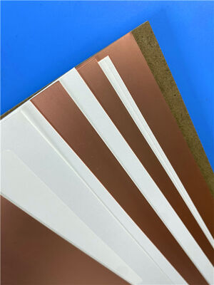
| Brand Name: | Rogers | Model Number: | RT/duroid 6202 |
|---|
Product Description
4-Layer Hybrid High-Frequency PCB – Rogers RT/duroid 6202 + FR-4 with Via-in-Pad & IPC Class 3
1. Material Overview – RT/duroid 6202 (Rogers)
RT/duroid® 6202 is a low-loss, low-dielectric-constant PTFE-based laminate from Rogers Corporation, reinforced with limited woven glass fabric. It is specifically designed for complex microwave structures that require both mechanical reliability and electrical stability .
The addition of woven glass reinforcement provides excellent dimensional stability (0.05 to 0.07 mils/inch) , enabling tight tolerance manufacturing for planar resistor applications and high-density multilayer circuits .
Key Material Characteristics
| Feature | Benefit |
| Ultra-Low Dk (2.94 ± 0.04 @ 10 GHz) | Reduces signal delay and crosstalk – ideal for high-frequency circuits up to 40 GHz+ . |
| Ultra-Low Df (0.0015 @ 10 GHz) | Minimizes insertion loss – critical for antenna feed networks, radar systems, and beamforming networks . |
| TCDk = +5 ppm/°C | Dielectric constant remains stable across temperature – essential for outdoor and aerospace applications . |
| X/Y CTE = 15 ppm/°C | Matches copper's CTE – reduces stress on plated through-holes and surface-mount components . |
| Dimensional Stability = 0.07 mm/m | Prevents double-etching and maintains tight positional tolerances . |
| Td = 500°C | Exceptional thermal robustness – supports lead-free assembly and harsh operating environments . |
| Low Moisture Absorption (0.04%) | Maintains electrical performance in humid conditions . |
| FR-4 Process Compatible | Unlike many PTFE materials, RT/duroid 6202 can be processed with standard FR-4 fabrication techniques . |
| Lead-Free Process Compatible | Fully supports 260°C peak reflow soldering . |
| UL 94 V-0 Flammability | Meets safety requirements for commercial and aerospace applications . |
| Typical Applications | |
| Market Segment | Specific Use Cases |
| Aerospace & Defense | Phased-array antennas, ground-based and airborne radar systems, commercial airline collision avoidance systems |
| Satellite Communications | Beamforming networks, GPS antennas, high-reliability space-grade circuits |
| High-Frequency Test & Measurement | Complex multilayer circuits with inter-layer connections |
| Microwave Backplanes | High-reliability power backplanes, RF distribution networks |
2. Material Datasheet – Consolidated Properties (RT/duroid 6202)
| Property | Direction | Typical Value | Unit | Test Method |
| Dielectric Constant (Dk) @ 10 GHz | Z | 2.94 ± 0.04 (≥0.020") | – | IPC-TM-650 2.5.5.5 |
| Dk @ 10 GHz (0.005" thickness) | Z | 3.06 ± 0.04 | – | IPC-TM-650 2.5.5.5 |
| Dk @ 10 GHz (0.010–0.015" thickness) | Z | 3.02 ± 0.04 | – | IPC-TM-650 2.5.5.5 |
| Dissipation Factor (Df) @ 10 GHz | Z | 0.0015 | – | IPC-TM-650 2.5.5.5 |
| Thermal Coefficient of Dk | Z | 5 | ppm/°C | IPC-TM-650 2.5.5.5; -50 to +150°C |
| Volume Resistivity | Z | 1 × 10⁶ | MΩ·cm | ASTM D257; Condition A |
| Surface Resistivity | Z | 1 × 10⁹ | MΩ | ASTM D257; Condition A |
| Thermal Conductivity | – | 0.68 | W/m·K | ASTM C518; 80°C |
| CTE X (-55 to 288°C) | X | 15 | ppm/°C | IPC-TM-650 2.4.41 |
| CTE Y (-55 to 288°C) | Y | 15 | ppm/°C | IPC-TM-650 2.4.41 |
| CTE Z (-55 to 288°C) | Z | 30 | ppm/°C | IPC-TM-650 2.4.41 |
| Td (Thermal Decomposition) | – | 500 | °C (TGA) | ASTM D3850 |
| Specific Heat | – | 0.93 (0.22) | J/g·K (BTU/lb/°F) | Calculated |
| Flammability | – | 94V-0 | Rating | UL 94 |
| Tensile Modulus | X,Y | 1007 (146) | MPa (kpsi) | ASTM D638; 23°C |
| Ultimate Stress | X,Y | 30 (4.3) | MPa (kpsi) | ASTM D638; 23°C |
| Ultimate Strain | X,Y | 4.9 | % | ASTM D638; 23°C |
| Compressive Modulus | Z | 1035 (150) | MPa (kpsi) | ASTM D638 |
| Copper Peel Strength (1 oz ED foil) | – | 9.1 (1.6) | lbs/in (N/mm) | IPC-TM-650 2.4.8 |
| Moisture Absorption | – | 0.04 | % | IPC-TM-650 2.6.2.1; ASTM D570; D23/24, D48/50 |
| Density | – | 2.1 | g/cm³ | ASTM D792 |
| Dimensional Stability | X,Y | 0.07 | mm/m (mil/in) | IPC-TM-650 2.4.3.9; after etch +E/150 |
Note on Dk Variation: Due to construction limitations, the dielectric constant of RT/duroid 6202 varies slightly by laminate thickness: 0.005" = 3.06 ± 0.04, 0.010–0.015" = 3.02 ± 0.04, ≥0.020" = 2.94 ± 0.04 .
Laminate Standard Availability
| Parameter | Options |
| Standard Thicknesses | 0.005" (0.127mm), 0.010" (0.254mm), 0.015" (0.381mm), 0.020" (0.508mm), 0.030" (0.762mm) |
| Standard Panel Sizes | 12" × 18", 24" × 18", 24" × 36" |
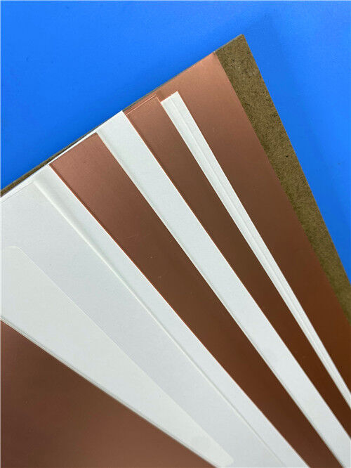
| Copper Cladding | EDC ½ oz, 1 oz; Rolled ½ oz, 1 oz, 2 oz; Reverse-treated; Resitive foil |
| Prepreg | RT/duroid 6202PR – available in roll or panel form |
3. Custom PCB – 4-Layer Hybrid RT/duroid 6202 + FR-4 with Via-in-Pad & IPC Class 3
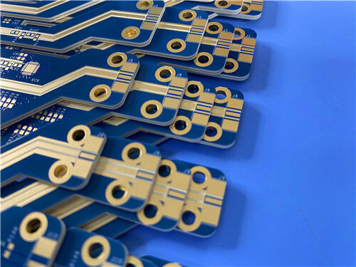
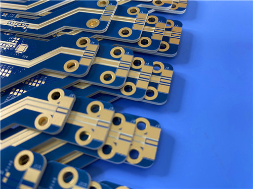
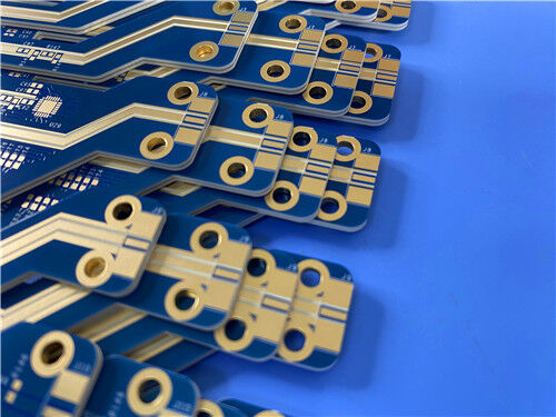
This 4-layer hybrid board demonstrates our capability to combine dissimilar materials (RT/duroid 6202 + FR-4) in a single, high-reliability PCB with IPC-6012 Class 3 compliance and advanced via-in-pad technology .
Basic Specifications
| Item | Specification |
| Layer Count | 4 layers |
| Stack-Up Type | Hybrid – Top: RT/duroid 6202 (0.127mm) + Prepreg (0.381mm) + Bottom: FR-4 (0.4mm) |
| Finished Board Thickness | 1.014 mm |
| Inner Layer Copper | 0.5 oz |
| Outer Layer Copper | 1 oz (top and bottom) |
| Surface Finish | ENIG (Electroless Nickel/Immersion Gold) |
| Solder Mask | Blue – both sides |
| Silkscreen | White – both sides |
| Panel Size | 110 mm × 35 mm (single unit, including tooling strips, mounting holes, and fiducials) |
Advanced Process Features
| Feature | Detail | Benefit |
| Via-in-Pad (VIP) | All vias: resin-plugged + plated-over copper cap | Enables component placement directly on vias – essential for dense layouts |
| Resin Plugging | Vias filled with resin and planarized | Provides flat surface for capping; prevents solder wicking |
| Capped Vias | Electroplated copper over filled vias | Ensures electrical continuity and mechanical reliability |
| ENIG Finish | Immersion Gold over Nickel | Excellent solderability, flat surface, corrosion resistance – ideal for fine-pitch and wire bonding |
| 25µm Hole Wall Copper | IPC-6012 Class 3 requirement | Ensures robust PTH reliability in harsh environments (aerospace, defense) |
| Hybrid Material Bonding | RT/duroid 6202 + FR-4 with appropriate prepreg | Balances RF performance and cost – high-frequency signals on RT/duroid, routing/power on FR-4 |
Stack-Up Design
This configuration ensures that critical RF paths reside entirely within RT/duroid 6202, while the bulk of digital and power routing uses FR-4 – giving you the best of both worlds .
4. Why RT/duroid 6202 + FR-4 Hybrid for This Design?
| Requirement | How RT/duroid 6202 + FR-4 Addresses It |
| High-frequency signal integrity (RF front-end) | RT/duroid 6202's Df = 0.0015 @ 10 GHz minimizes insertion loss – critical for antenna feed networks and radar systems . |
| Temperature-stable performance | TCDk = +5 ppm/°C ensures stable impedance over -50°C to +150°C – essential for aerospace and outdoor applications . |
| Mechanical reliability | X/Y CTE = 15 ppm/°C matches copper – reduces PTH stress and ensures reliable surface-mount soldering . |
| Dimensional tolerance | Dimensional stability = 0.07 mm/m – enables tight positional tolerances for complex microwave circuits . |
| Cost-effectiveness | Hybrid construction places expensive RT/duroid only where needed (RF layers), using FR-4 for routing/power – reducing material cost . |
| IPC Class 3 reliability | 25µm hole wall copper and robust material properties meet the highest reliability standards for aerospace and defense. |
| Dense BGA routing | Via-in-pad support (resin plug + cap) allows breakout from fine-pitch components. |
Comparison Table – RT/duroid 6202 vs. Standard FR-4 vs. High-End RF Materials
| Parameter | RT/duroid 6202 | Standard FR-4 (High-Tg) | High-End PTFE (e.g., RT/duroid 5880) |
| Dk (@ 10 GHz) | 2.94 ± 0.04 | ~4.2–4.5 | ~2.20 |
| Df (@ 10 GHz) | 0.0015 | ~0.015–0.020 | ~0.0009 |
| TCDk (ppm/°C) | +5 | ~+50 to +100 | ~0 (very low) |
| Td (TGA) | 500°C | ~340°C | ~500°C |
| CTE X/Y (ppm/°C) | 15/15 | ~14–16 | ~17–20 |
| CTE Z (ppm/°C) | 30 | ~50–70 | ~30–40 |
| Moisture Absorption | 0.04% | ~0.3–0.5% | ~0.02% |
| Dimensional Stability (mm/m) | 0.07 | ~0.10–0.20 | ~0.05–0.10 |
| Glass Reinforcement | Limited woven glass | E-glass | No glass (pure PTFE) |
| FR-4 Process Compatibility | Yes | Yes | Limited (sodium etch) |
| Relative Cost | High | Low | Very High |
| Primary Application | Radar, phased arrays, high-reliability RF | General digital | Space-grade, ultra-low-loss |
Application Areas
Phased-Array Antennas
Airborne & Ground-Based Radar
Commercial Airline Collision Avoidance Systems
Power Backplanes (High-Frequency)
Beamforming Networks
Q1: What makes RT/duroid 6202 different from standard FR-4?
A: RT/duroid 6202 offers significantly lower Dk (2.94 vs. ~4.2–4.5) , lower Df (0.0015 vs. ~0.015–0.020) , TCDk = +5 ppm/°C (very stable across temperature), X/Y CTE matched to copper (15 ppm/°C) , and excellent dimensional stability (0.07 mm/m) – all within a PTFE-based glass-reinforced system compatible with FR-4 processes .
Q2: Why use a hybrid stack-up (RT/duroid + FR-4) instead of all-RT/duroid?
A: Cost optimization. RT/duroid is significantly more expensive than FR-4. By placing RT/duroid only on the top layer (where RF signals are launched) and using FR-4 for routing and power distribution, we reduce material cost while maintaining critical RF performance. Hybrid construction is widely used in RF + control board designs .
Q3: Is RT/duroid 6202 compatible with lead-free soldering?
A: Yes. RT/duroid 6202 is lead-free process compatible and supports 260°C peak reflow soldering .
Q4: Can all vias be resin-plugged and capped (via-in-pad)?
A: Yes. Our manufacturing process supports resin plugging + electroplated capping for all vias. This is standard for this 4-layer design and enables component placement directly over vias.
Q5: What is IPC-6012 Class 3, and why is it important?
A: IPC-6012 Class 3 is the highest reliability class for rigid printed boards, requiring 25µm minimum hole wall copper, stringent inspection criteria, and proven thermal/mechanical reliability. It is required for aerospace, defense, medical, and high-reliability telecom applications.
Q6: What surface finishes are available for this hybrid board?
A: ENIG (Immersion Gold) is specified for this design. We also offer immersion silver, immersion tin, ENEPIG, and OSP – depending on your application requirements.
Contact Us
As a specialized PCB supplier based in China, we have extensive experience with Rogers RT/duroid materials, hybrid stack-ups (RT/duroid + FR-4) , and complex via-in-pad processes.
We provide:
For technical inquiries, stack-up review, or quotation requests, please contact our sales team directly. We are ready to support your high-frequency aerospace, defense, and telecom projects.
Enter Your Message

RO4350B, 4003C; Rogers 5880, 5870, 6002, 6010, 6006, 6035; RO3003, RO3035, RO3006, RO3010, RO3210,RO3203
TLX-8, TLX-6, TLX-9, TLX-0, TLX-7, TLY-3, TLY-5, RF-35TC, RF-60TC, RF-35A2, RF-60A, AD450, AD600, TMM4, TC350
| Shenzhen Bicheng Electronics Technology Co., Ltd |
| 6-11C Shidai Jingyuan Fuyong Town, Baoan District, Shenzhen City, Guangdong Province, China |
| 86-755-27374946 |
| sales30@bichengpcb.com |