


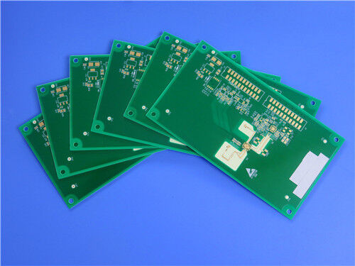
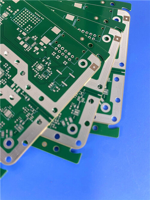

20-Layer TU-872/SLK TG200 FR4 HDI PCB board with Impedance control | 3.0mm Thick | Nickel-Palladium-Gold Finish
Contact Person : Sally Mao
Phone Number : 86-755-27374847
WhatsApp : +8618277967574
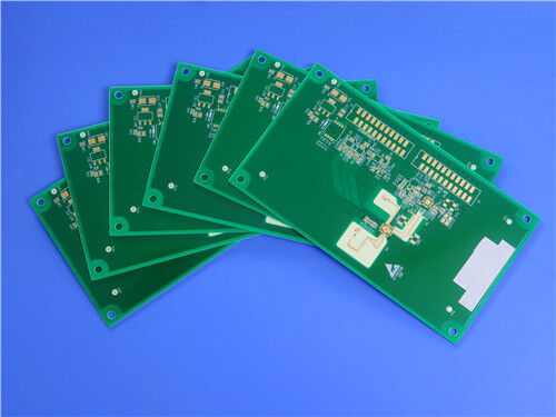
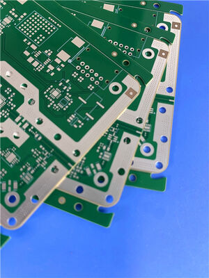
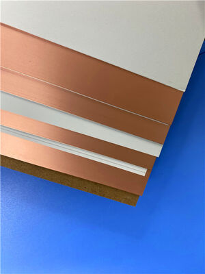
| Brand Name: | Rogers | Model Number: | RO4003C + S1000-2M |
|---|
Product Description
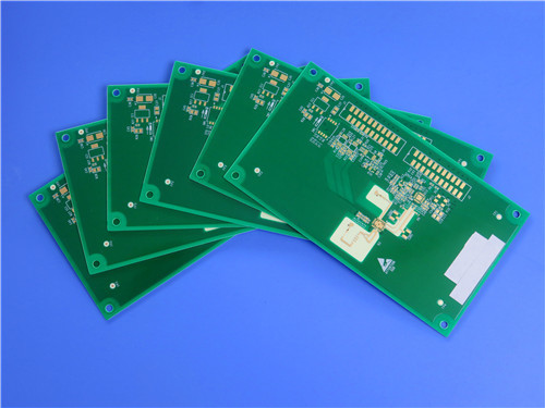
Hybrid High-Frequency PCB Solution – RO4003C + S1000-2M 8-Layer Custom Board
Q: What is this hybrid PCB solution, and what does it achieve?
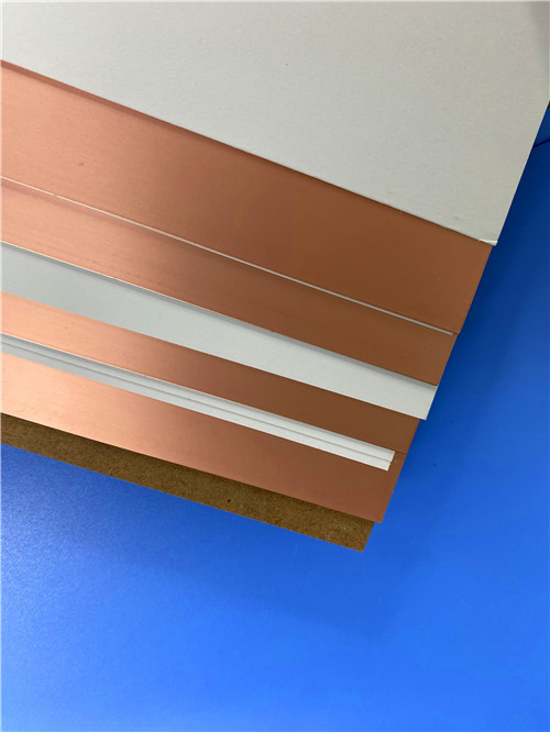
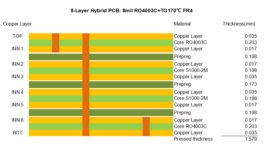
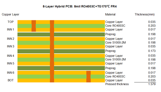
A: This solution combines Rogers RO4003C (a high-frequency hydrocarbon ceramic laminate) with S1000-2M (a high-performance FR-4–type material from Shengyi) in a single 8-layer hybrid stack-up. The top and bottom layers use 0.203mm RO4003C for optimal RF signal integrity, while the inner core uses S1000-2M for cost-effective, reliable multilayer routing.
The reference product is specified as:
This hybrid design delivers high-frequency performance where it matters (outer layers) and cost-effective, high-density routing inside – ideal for RF front-ends, 5G small cells, and radar modules.
Key Takeaways
| Key Highlight | Description | |
| ① | Hybrid Stack-Up | Combines Rogers RO4003C (RF-grade) and Shengyi S1000-2M (high-Tg FR-4) in one board – balancing performance and cost. |
| ② | RF-Optimized Outer Layers | Top and bottom RO4003C layers provide low Dk (3.38±0.05) and low Df (0.0027 @ 10GHz) for clean signal launch and termination. |
| ③ | High-Thermal Core | S1000-2M core offers Tg = 185°C (DMA), Td = 355°C, and excellent CAF/IST reliability – ideal for high-layer-count inner routing. |
| ④ | Advanced HDI Capabilities | Supports blind vias (L1–L2, L7–L8) and resin-filled vias (0.2/0.25/0.35mm) – enabling dense BGA breakout and impedance control. |
| ⑤ | RoHS & Lead-Free Compatible | Both materials are fully compatible with lead-free assembly processes (peak reflow >260°C). |
| ⑥ | Proven Reliability | S1000-2M has passed IST >2000 cycles, CAF >1000 hours, and 6× 260°C reflow – ensuring long-term field performance. |
1. Material Overview – RO4003C (Rogers)
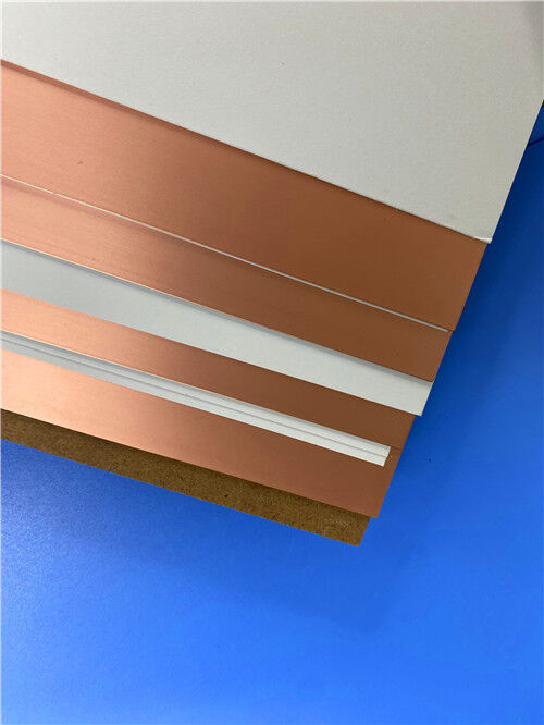
RO4003C is a hydrocarbon ceramic laminate from Rogers Corporation, specifically designed for high-frequency RF/microwave applications. It bridges the performance gap between PTFE-based materials and standard FR-4, offering:
Low and stable Dk – 3.38 ± 0.05 (process) / 3.55 (design) from 8–40 GHz
Low dissipation factor – 0.0027 @ 10GHz, 0.0021 @ 2.5GHz
Very low Dk temperature coefficient – +40 ppm/°C (stable over -50°C to 150°C)
High Tg > 280°C (TMA) and Td = 425°C – exceptional thermal robustness
Low Z-axis CTE – ~46 ppm/°C – ensures reliable plated through-holes
FR-4 process compatible – no sodium etch or special via prep required
Key Electrical Properties (RO4003C):
| Property | Value | Condition |
| Dielectric Constant (Process Dk) | 3.38 ± 0.05 | 10 GHz / 23°C |
| Dielectric Constant (Design Dk) | 3.55 | 8–40 GHz |
| Dissipation Factor (Df) | 0.0027 / 0.0021 | 10 GHz / 2.5 GHz |
| Tεr (Thermal Coefficient of Dk) | +40 ppm/°C | -50°C to 150°C |
| Volume Resistivity | 1.7 × 10¹⁰ MΩ·cm | COND A |
| Surface Resistivity | 4.2 × 10⁹ MΩ | COND A |
| Electrical Strength | 31.2 kV/mm (780 V/mil) | 0.51mm |
| Moisture Absorption | 0.06% | 48h immersion @50°C |
Mechanical & Thermal (RO4003C):
| Property | X / Y / Z | Value |
| Tensile Modulus | X / Y | 19,650 / 19,450 MPa (2,850 / 2,821 ksi) |
| Tensile Strength | X / Y | 139 / 100 MPa (20.2 / 14.5 ksi) |
| Flexural Strength | – | 276 MPa (40 kpsi) |
| CTE | X / Y / Z | 11 / 14 / 46 ppm/°C (-55 to 288°C) |
| Tg (TMA) | – | >280°C |
| Td (TGA) | – | 425°C |
| Thermal Conductivity | – | 0.71 W/m·K |
| Copper Peel Strength | – | 1.05 N/mm (6.0 pli) |
Standard Thicknesses Available: 0.008" (0.203mm), 0.012", 0.016", 0.020", 0.032", 0.060" – our design uses 0.203mm (8 mil) for outer layers.
Applications: Automotive radar (77GHz), 5G mmWave antennas, point-to-point radios, satellite communications, test & measurement equipment.
2. Material Overview – S1000-2M (Shengyi)
S1000-2M is a high-performance, high-Tg FR-4–type laminate from Shengyi Technology, designed for multilayer boards requiring excellent thermal reliability and CAF resistance. It is widely used in:
High-layer-count backplanes and server boards
Automotive and industrial electronics
Base station equipment
Any application requiring lead-free soldering compatibility and long-term reliability
Key Properties (S1000-2M):
| Property | Condition | Spec | Typical Value |
| Tg (DMA) | – | ≥180°C | 185°C |
| Td (5% wt loss) | – | ≥340°C | 355°C |
| CTE (Z-axis, pre-Tg) | – | ≤60 ppm/°C | 41 ppm/°C |
| CTE (Z-axis, post-Tg) | – | ≤300 ppm/°C | 208 ppm/°C |
| CTE (Z-axis, 50–260°C) | – | ≤3.0% | 2.40% |
| T260 / T288 / T300 | TMA | ≥30 / ≥5 / ≥2 min | 60 / 30 / 15 min |
| Thermal Stress (288°C solder dip) | – | >10s, no delam | >100s, no delam |
| Peel Strength (1 oz) | 288°C/10s | ≥1.05 N/mm | 1.3 N/mm |
| Water Absorption | D-24/23 | ≤0.5% | 0.08% |
| CTI (Comparative Tracking Index) | IEC60112 | PLC3 (175–250V) | PLC3 (200V) |
| Volume Resistivity | After moisture / E-24/125 | ≥10⁶ / ≥10³ MΩ·cm | 6.79×10⁷ / 2.19×10⁸ |
| Surface Resistivity | After moisture / E-24/125 | ≥10⁴ / ≥10³ MΩ | 3.16×10⁶ / 2.24×10⁷ |
| Dielectric Constant (Dk) | @1GHz / @1MHz | – / ≤5.4 | 4.6 / 4.9 |
| Dissipation Factor (Df) | @1GHz / @1MHz | – / ≤0.035 | 0.018 / 0.015 |
| Flammability | UL94 | V-0 | V-0 |
Reliability Validation (S1000-2M):
24-layer board (0.13mm core, 4.0mm total thickness, 0.35mm min hole, aspect ratio 11.5:1) – passed 5× 260°C lead-free reflow.
IST (Interconnect Stress Test) – 20-layer board, >2000 power cycles (room temp to 150°C), no failure.
CAF (Conductive Anodic Filament) Test – 20-layer, TH–TH 16/20 mil spacing, >1000 hours at 65°C/87%RH/100V DC, passed.
3. Custom PCB – 8-Layer Hybrid Stack-Up
This board represents our capability to integrate dissimilar materials into a single, high-reliability PCB with advanced HDI features.
Basic Specifications
| Item | Specification |
| Layer Count | 8 layers |
| Stack-Up Type | Hybrid – Top/Bottom: RO4003C (0.203mm); Inner Core: S1000-2M |
| Finished Board Thickness | 1.6mm |
| Outer Layer Copper | 1 oz (both top and bottom) |
| Inner Layer Copper | Mixed – 0.5 oz / 1 oz (designed per signal/power requirements) |
| Surface Finish | ENIG (Immersion Gold) – excellent for fine-pitch components and wire bonding |
| Solder Mask / Legend | Green solder mask / White silkscreen (both sides) |
| Panel Size | 273mm × 185mm (1 piece, including manufacturing borders) |
Advanced HDI & Via Features
| Feature | Detail | Benefit |
| Blind Vias | L1–L2, L7–L8 | Eliminates stub effects on RF layers; improves signal integrity |
| Resin-Filled Vias | 0.2mm, 0.25mm, 0.35mm diameters | Provides flat, solderable surfaces; enables via-in-pad design for BGA routing |
| Mixed Copper Weights | 0.5 oz inner / 1 oz outer | Optimizes impedance control (inner) and current capacity (outer) |
| Hybrid Material Bonding | RO4003C + S1000-2M with compatible prepreg | Balances RF performance and mechanical strength across the board |
Hybrid Stack-Up
This configuration ensures that critical RF paths reside entirely within RO4003C, while the bulk of digital and power layers use S1000-2M – giving you the best of both worlds.
Comparison Table – RO4003C vs. S1000-2M vs. Typical FR-4
| Parameter | RO4003C (Rogers) | S1000-2M (Shengyi) | Standard FR-4 (High-Tg) |
| Dk @ 1GHz / 10GHz | 3.38 (10GHz) / 3.55 (8–40GHz) | ~4.6 (1GHz) / – | ~4.2–4.5 |
| Df @ 10GHz / 1GHz | 0.0027 (10GHz) | 0.018 (1GHz) | 0.015–0.020 |
| Tg (DMA/TMA) | >280°C (TMA) | 185°C (DMA) | ~170–180°C |
| Td (TGA) | 425°C | 355°C | ~340°C |
| CTE Z-axis (pre/post Tg) | ~46 ppm/°C | 41 / 208 ppm/°C | ~50–70 / 250–350 |
| Thermal Conductivity | 0.71 W/m·K | – | ~0.3–0.5 |
| Moisture Absorption | 0.06% | 0.08% | ~0.3–0.5% |
| Process Compatibility | FR-4 compatible | FR-4 standard | FR-4 standard |
| Primary Application | RF/mmWave front-end | High-layer-count digital/backplane | General digital |
| Relative Cost | Higher | Mid | Low |
Application Areas – Where This Hybrid PCB Excels
Q1: Why choose a hybrid stack-up instead of all-RO4003C?
A: Cost optimization. RO4003C is significantly more expensive than FR-4-type materials. By using RO4003C only on the outer layers where RF performance matters, and S1000-2M for the inner layers, we reduce material cost while maintaining critical RF performance.
Q2: Are RO4003C and S1000-2M compatible in terms of lamination?
A: Yes. Both materials are thermoset systems compatible with standard FR-4 lamination cycles. We use transition prepreg layers to ensure reliable bonding between the different core materials.
Q3: Can you support impedance-controlled designs on this hybrid board?
A: Absolutely. We can calculate and control differential/single-ended impedances on both RO4003C and S1000-2M layers based on your stack-up and trace geometry requirements.
Q4: What is the minimum via diameter you can drill and fill?
A: We support mechanical drilling down to 0.15mm and resin filling for vias as small as 0.2mm (as specified in this design: 0.2, 0.25, 0.35mm).
Q5: Is ENIG (Immersion Gold) suitable for RF applications?
A: Yes. ENIG provides a flat, solderable surface and good corrosion resistance. For very high-frequency (mmWave) applications, some designers prefer immersion silver to avoid the nickel layer, but ENIG is widely accepted for most RF designs up to 40GHz.
Q6: What is the lead time for this hybrid 8-layer board?
A: Typical prototype lead time is 10–15 working days for this stack-up with blind vias and resin filling. Volume production lead time can be shortened with advance material sourcing.
Q7: Do you provide stack-up design assistance?
A: Yes. Our engineering team can help you define layer assignments, calculate impedance, and optimize the hybrid stack-up for manufacturability and signal integrity.
Q8: What are the storage conditions for S1000-2M prepreg?
A: Short-term (<3 months): <23°C, <50% RH. Long-term (up to 6 months): 5°C. Always keep wrapped in moisture-proof material and avoid UV/strong light.
Q9: Can you build this board with LoPro foil on RO4003C for lower loss?
A: Yes. Rogers offers RO4003C with LoPro® (reverse-treated) foil for reduced insertion loss. Please specify this requirement in your inquiry.
Q10: Is this design compliant with IPC standards?
A: Yes. RO4003C conforms to IPC-4103 /10, and S1000-2M meets applicable IPC-4101 specifications. Our manufacturing process is IPC Class 2/3 compliant.
Contact Us
As a specialized PCB supplier based in China, we have extensive experience with hybrid high-frequency materials and complex HDI processes. Whether you need a prototype or volume production, we provide:
Full material traceability
Impedance testing (TDR)
X-ray inspection for blind vias
Electrical testing (flying probe / fixture)
Quick-turn services available
For technical inquiries, quotation requests, or design review support, please contact our sales team directly. We look forward to helping you bring your high-frequency designs to life.
Enter Your Message

RO4350B, 4003C; Rogers 5880, 5870, 6002, 6010, 6006, 6035; RO3003, RO3035, RO3006, RO3010, RO3210,RO3203
TLX-8, TLX-6, TLX-9, TLX-0, TLX-7, TLY-3, TLY-5, RF-35TC, RF-60TC, RF-35A2, RF-60A, AD450, AD600, TMM4, TC350
| Shenzhen Bicheng Electronics Technology Co., Ltd |
| 6-11C Shidai Jingyuan Fuyong Town, Baoan District, Shenzhen City, Guangdong Province, China |
| 86-755-27374946 |
| sales30@bichengpcb.com |