


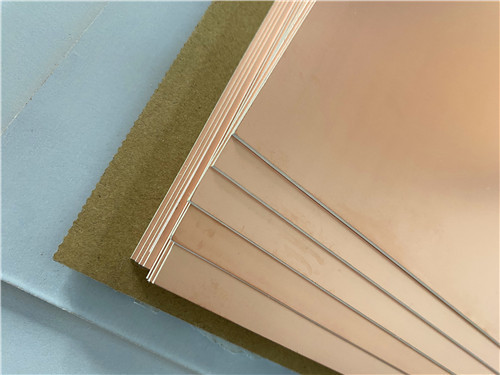
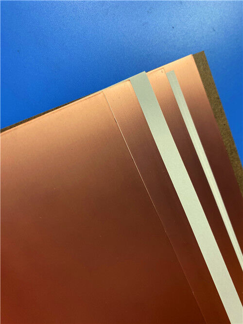
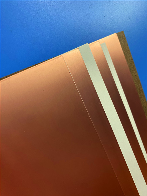

F4BTMS350 DK3.5 with RTF low-roughness copper foil High-Reliability Laminate and Custom 2layer PCB Solutions
Contact Person : Sally Mao
Phone Number : 86-755-27374847
WhatsApp : +8618277967574
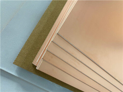

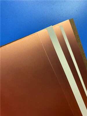
| Brand Name: | Rogers | Model Number: | RO4535 |
|---|
Product Description
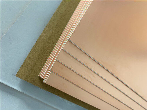
Rogers RO4535™ is a cost-performance antenna-grade laminate from the RO4500™ series, engineered specifically to meet the demands of wireless antenna markets. It extends the proven RO4000® product family into antenna applications by combining a ceramic-filled, glass-reinforced hydrocarbon dielectric with the controlled electrical performance, low loss, and passive intermodulation (PIM) response required for mobile infrastructure microstrip antennas.
A key advantage of RO4535 is its compatibility with conventional FR-4 and high-temperature lead-free solder processing. Unlike traditional PTFE-based laminates, it does not require special plated-through-hole preparation. This makes RO4535 an affordable alternative to conventional PTFE antenna technologies, allowing designers to optimize both cost and RF performance. The material is available with Rogers’ RoHS-compliant flame-retardant technology for applications requiring UL94 V-0 certification.
Key Properties at a Glance (RO4535):
| Property | Typical Value | Test Condition |
| Dielectric Constant (Dk, process) | 3.44 ± 0.08 | 10 GHz / 23°C |
| Dissipation Factor (Df) | 0.0032 / 0.0037 | 2.5 GHz / 10 GHz |
| PIM (typical) | -157 dBc | Reflected 43 dBm swept tones, 1900 MHz |
| Dielectric Strength | >500 V/mil | 0.51 mm, Z-direction |
| Dimensional Stability | <0.5 mm/m | After etch |
| CTE - X / Y / Z | 16 / 17 / 50 ppm/°C | -55°C to +288°C |
| Thermal Conductivity | 0.6 W/m·K | 80°C |
| Glass Transition Temperature (Tg) | >280°C | TMA |
| Moisture Absorption | 0.09% | D48/50 |
| Density | 1.9 g/cm³ | — |
| Copper Peel Strength | 5.1 lb/in (0.9 N/mm) | 1 oz EDC after solder float |
| Flammability Rating | UL 94 V-0 | — |
| Lead-Free Process Compatible | Yes | — |
Note: PIM performance is strongly influenced by copper foil choice. The typical -157 dBc value is based on reverse-treated electrodeposited copper foil tested on 0.060" laminate. Standard EDC foil typically provides PIM performance better than -145 dBc.
Applications
Cellular Infrastructure Base Station Antennas
VHF/UHF Antennas
WiMAX Antenna Networks
Mobile Infrastructure Antenna Systems
The RO4500 series offers a Dk range of approximately 3.3 to 3.5 and a low-loss range of 0.0020 to 0.0037 at 2.5 GHz, giving antenna designers flexibility to optimize gain, bandwidth, and physical size.
Custom PCB Manufacturing on RO4535
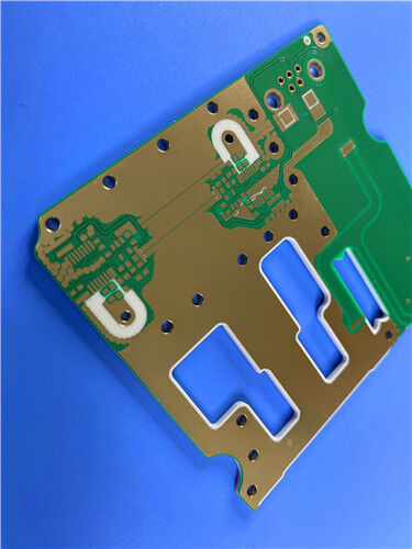
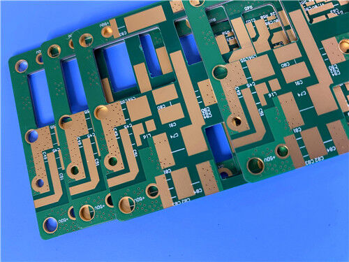
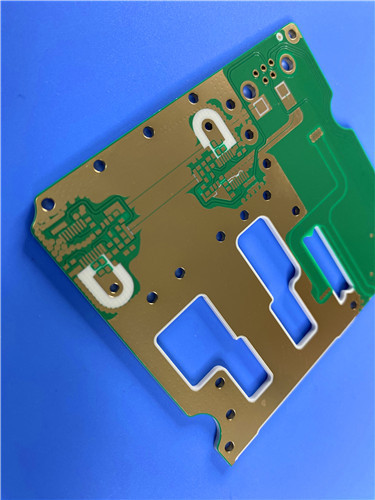
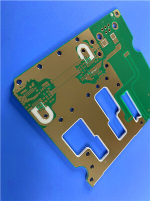
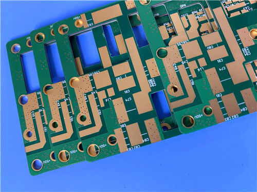
As a specialized manufacturer of high-frequency printed circuit boards, we offer fabrication services using Rogers RO4535 and other advanced laminate materials. The following specification details a representative 2-layer rigid PCB implementation:
PCB Construction Details:
| Parameter | Specification |
| Base Material | Rogers RO4535 |
| Layer Count | 2-layer rigid |
| Board Dimensions | 63 mm × 79.5 mm per panel, ±0.15 mm |
| Finished Thickness | 1.6 mm |
| Copper Weight | 1 oz (35 μm) outer layers |
| Minimum Trace/Space | 4 / 6 mils |
| Minimum Hole Size | 0.25 mm |
| Via Structure | No blind or buried vias |
| Via Plating Thickness | 20 μm |
| Surface Finish | Immersion Silver |
| Solder Mask | Blue, top and bottom |
| Silkscreen | White, top side only |
| Electrical Test | 100% prior to shipment |
| Artwork Format | Gerber RS-274-X |
| Quality Standard | IPC-Class-2 |
Material Advantages
Cost-Performance Balance for Antenna Applications:
RO4535 is positioned as an affordable alternative to conventional PTFE antenna materials. By using a ceramic-filled, glass-reinforced hydrocarbon system, it delivers controlled dielectric constant, low loss, and good PIM performance while remaining compatible with standard PCB fabrication and lead-free assembly.
Controlled Electrical Performance:
The process Dk of 3.44 ± 0.08 at 10 GHz supports repeatable impedance control. The dissipation factor is 0.0032 at 2.5 GHz and 0.0037 at 10 GHz, enabling efficient antenna feed networks and microstrip radiating elements with reduced signal loss.
Excellent PIM Response:
RO4535 supports low PIM performance, with typical values of -157 dBc using reflected 43 dBm swept tones at 1900 MHz when paired with appropriate reverse-treated copper foil. This helps reduce PIM-related yield loss and supports clean antenna system performance.
Thermal and Mechanical Stability:
The CTE values of 16 ppm/°C in X, 17 ppm/°C in Y, and 50 ppm/°C in Z are similar to copper, reducing stress in printed circuit board antennas. A Tg exceeding 280°C supports lead-free processing and contributes to low z-axis CTE and reliable plated through-holes. Dimensional stability of less than 0.5 mm/m after etch supports repeatable circuit registration and good panel yields.
Improved Power Handling:
Thermal conductivity of 0.6 W/m·K is higher than equivalent PTFE/woven-glass materials, allowing antenna designs with increased power-handling capability.
FR-4-Compatible Processing:
RO4535 is fully compatible with conventional FR-4 and high-temperature lead-free solder processes. It does not require the specialized plated-through-hole treatment needed for traditional PTFE laminates, simplifying fabrication and reducing process cost.
Environmental Compliance:
RO4535 is RoHS compliant, available with UL94 V-0 flame-retardant technology, and lead-free process compatible.
Processing and Design Considerations
Quality and Availability
All boards are manufactured in compliance with IPC-Class-2 quality standards. 100% electrical testing is performed prior to shipment to ensure functional integrity.
Our production capability extends to worldwide availability, with flexible logistics support for both prototype and volume requirements. We offer rapid turnaround and competitive pricing while maintaining strict process control.
For inquiries about custom stack-ups, panel sizes, copper foil options, or other configurations, please contact our sales engineering team—we are ready to support your high-frequency circuit board requirements.
Enter Your Message

RO4350B, 4003C; Rogers 5880, 5870, 6002, 6010, 6006, 6035; RO3003, RO3035, RO3006, RO3010, RO3210,RO3203
TLX-8, TLX-6, TLX-9, TLX-0, TLX-7, TLY-3, TLY-5, RF-35TC, RF-60TC, RF-35A2, RF-60A, AD450, AD600, TMM4, TC350
| Shenzhen Bicheng Electronics Technology Co., Ltd |
| 6-11C Shidai Jingyuan Fuyong Town, Baoan District, Shenzhen City, Guangdong Province, China |
| 86-755-27374946 |
| sales30@bichengpcb.com |