


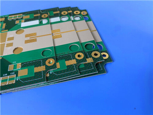
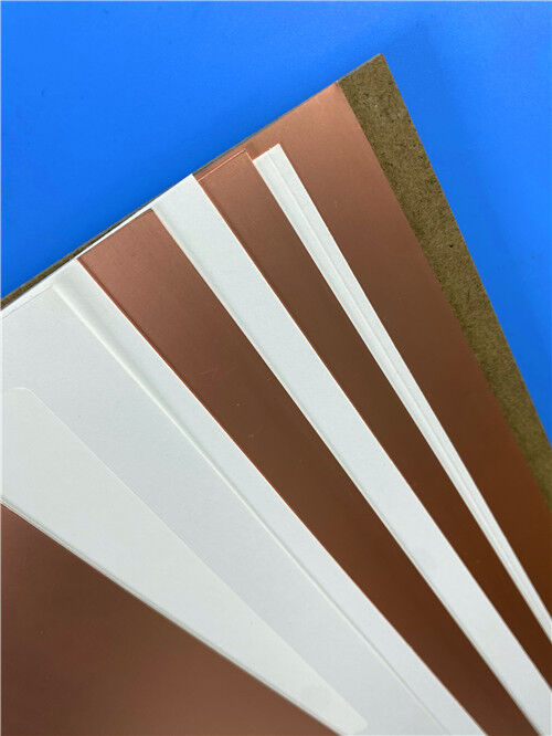
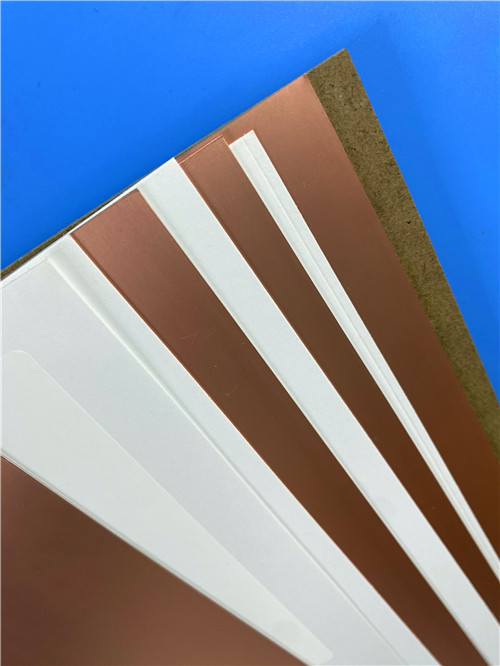

Rogers RO4360G2 laminate manufacture 2-layer 12mil thick PCB(ENEPIG) be paired with RO4400™ prepreg and lower-Dk RO4000® laminates in multilayer designs
Contact Person : Sally Mao
Phone Number : 86-755-27374847
WhatsApp : +8618277967574
| Brand Name: | Rogers | Model Number: | RT/duroid 6202 |
|---|
Product Description
In the design of complex microwave structures—from phased array antennas to airborne radar systems—material selection plays a decisive role in achieving reliable, repeatable performance. Rogers RT/duroid 6202 is a low-loss, low-dielectric-constant laminate with limited woven glass reinforcement, engineered to deliver the electrical and mechanical stability essential for demanding high-frequency applications.
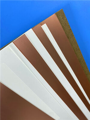
RT/duroid 6202 is available with ½ oz. to 2 oz./ft² electrodeposited or rolled copper foil on dielectric thicknesses ranging from 0.005" to 0.060" (0.127 mm to 1.524 mm). Its excellent dimensional stability (0.05 to 0.07 mils/inch) often eliminates the need for double etching to achieve tight positional tolerances, simplifying fabrication and improving yield.
Key Properties at a Glance:
| Property | Direction | Typical Value | Unit | Test Method |
| Dielectric Constant (Dk) @ 10 GHz | Z | 2.94 ± 0.04 (≥0.020") | – | IPC-TM-650 2.5.5.5 |
| Dk @ 10 GHz (0.005" thickness) | Z | 3.06 ± 0.04 | – | IPC-TM-650 2.5.5.5 |
| Dk @ 10 GHz (0.010–0.015" thickness) | Z | 3.02 ± 0.04 | – | IPC-TM-650 2.5.5.5 |
| Dissipation Factor (Df) @ 10 GHz | Z | 0.0015 | – | IPC-TM-650 2.5.5.5 |
| Thermal Coefficient of Dk | Z | 5 | ppm/°C | IPC-TM-650 2.5.5.5; -50 to +150°C |
| Volume Resistivity | Z | 1 × 10⁶ | MΩ·cm | ASTM D257; Condition A |
| Surface Resistivity | Z | 1 × 10⁹ | MΩ | ASTM D257; Condition A |
| Thermal Conductivity | – | 0.68 | W/m·K | ASTM C518; 80°C |
| CTE X (-55 to 288°C) | X | 15 | ppm/°C | IPC-TM-650 2.4.41 |
| CTE Y (-55 to 288°C) | Y | 15 | ppm/°C | IPC-TM-650 2.4.41 |
| CTE Z (-55 to 288°C) | Z | 30 | ppm/°C | IPC-TM-650 2.4.41 |
| Td (Thermal Decomposition) | – | 500 | °C (TGA) | ASTM D3850 |
| Specific Heat | – | 0.93 (0.22) | J/g·K (BTU/lb/°F) | Calculated |
| Flammability | – | 94V-0 | Rating | UL 94 |
| Tensile Modulus | X,Y | 1007 (146) | MPa (kpsi) | ASTM D638; 23°C |
| Ultimate Stress | X,Y | 30 (4.3) | MPa (kpsi) | ASTM D638; 23°C |
| Ultimate Strain | X,Y | 4.9 | % | ASTM D638; 23°C |
| Compressive Modulus | Z | 1035 (150) | MPa (kpsi) | ASTM D638 |
| Copper Peel Strength (1 oz ED foil) | – | 9.1 (1.6) | lbs/in (N/mm) | IPC-TM-650 2.4.8 |
| Moisture Absorption | – | 0.04 | % | IPC-TM-650 2.6.2.1; ASTM D570; D23/24, D48/50 |
| Density | – | 2.1 | g/cm³ | ASTM D792 |
| Dimensional Stability | X,Y | 0.07 | mm/m (mil/in) | IPC-TM-650 2.4.3.9; after etch +E/150 |
Note: Dk varies by thickness—0.005" laminates are 3.06 ± 0.04; 0.010" and 0.015" laminates are 3.02 ± 0.04; ≥0.020" laminates are 2.94 ± 0.04.
| PCB Capability (RT/duroid 6202) | ||
| PCB Material: | PTFE Ceramic Woven Glass Reinforced | |
| Designation: | RT/duroid 6202 | |
| Dielectric constant: | Thickness | DK |
| 5mil (0.127mm) | 3.06 ± 0.04 | |
| 10mil (0.254mm) | 3.02 ± 0.04 | |
| 15mil (0.381mm) | 3.02 ± 0.04 | |
| 20mil (0.508mm) | 2.94 ± 0.04 | |
| 30mil (0.762mm) | 2.94 ± 0.04 | |
| Layer count: | Single layer, Double layer, Multi-layer, Hybrid PCB | |
| Copper weight: | 1oz (35µm), 2oz (70µm) | |
| Dielectric thickness: | 5mil (0.127mm), 10mil (0.24mm), 15mil (0.381mm), 20mil (0.508mm), 30mil(0.762mm) | |
| PCB size: | ≤400mm X 500mm | |
| Solder mask: | Green, Black, Blue, Yellow, Red etc. | |
| Surface finish: | Bare copper, HASL, ENIG, OSP, Immersion tin, Immersion silver, Pure gold, ENEPIG etc.. | |
Applications
Phased Array Antennas – Precise element-to-element phase control
Ground-Based and Airborne Radar Systems – Reliable performance in harsh environments
GPS Antennas – Stable Dk for accurate positioning
Power Backplanes – Low loss at high frequencies
Commercial Airline Collision Avoidance – Mission-critical reliability
Beam Forming Networks – Consistent electrical performance across arrays
High-Reliability Complex Multilayer Circuits – Dimensional stability for demanding stack-ups
Custom PCB Manufacturing on RT/duroid 6202
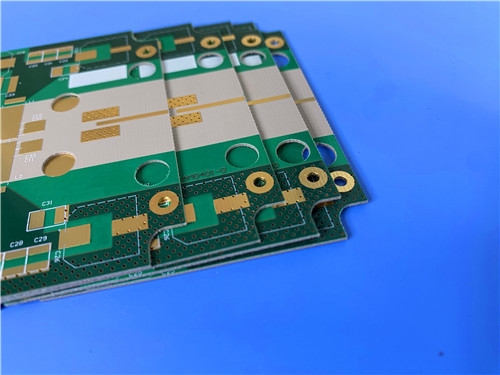
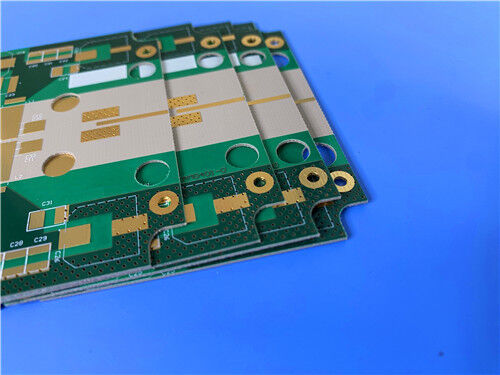
As a specialized manufacturer of high-frequency printed circuit boards, we offer comprehensive fabrication services using Rogers RT/duroid 6202 and other advanced materials. The following specification details a representative 2-layer rigid PCB implementation:
PCB Construction Details:
| Parameter | Specification |
| Base Material | Rogers RT/duroid 6202 |
| Layer Count | 2-layer rigid |
| Board Dimensions | 42.36mm × 21.9mm per panel |
| Finished Thickness | 0.6mm |
| Copper Weight | 1 oz (1.4 mils) outer layers |
| Minimum Trace/Space | 4 / 7 mils |
| Minimum Hole Size | 0.4mm |
| Via Structure | No blind or buried vias |
| Via Plating Thickness | 20 μm |
| Surface Finish | ENIG (Electroless Nickel Immersion Gold) |
| Solder Mask | Green, top side only |
| Silkscreen | White, top side only |
| Electrical Test | 100% prior to shipment |
| Artwork Format | Gerber RS-274-X |
| Quality Standard | IPC-Class-2 |
PCB Statistics:
| Metric | Count |
| Components | 13 |
| Total Pads | 20 |
| Through-Hole Pads | 11 |
| Top SMT Pads | 9 |
| Bottom SMT Pads | 0 |
| Vias | 6 |
| Nets | 2 |
Low Loss for High-Frequency Performance:
RT/duroid 6202 offers a dissipation factor of just 0.0015 at 10 GHz, minimizing signal attenuation in transmission lines and ensuring excellent high-frequency performance across microwave and millimeter-wave bands.
Excellent Dimensional Stability:
With dimensional stability of 0.05 to 0.07 mils/inch—achieved through limited woven glass reinforcement—RT/duroid 6202 often eliminates double etching, reduces registration errors, and improves manufacturing yields for tight-tolerance designs.
Matched In-Plane Expansion:
The X- and Y-axis CTE of 15 ppm/°C is closely matched to copper, reducing stress on plated through-holes and improving reliability through thermal cycling. The low Z-axis CTE of 30 ppm/°C further enhances dimensional stability in multilayer constructions.
Low Thermal Coefficient of Dk:
At just 5 ppm/°C over -50 to +150°C, the dielectric constant remains highly stable across temperature, ensuring consistent electrical performance in environments subject to wide temperature swings.
Thermal and Moisture Resistance:
Very Low Etch Shrinkage:
The material exhibits very low etch shrinkage, contributing to precise feature definition and repeatable circuit performance.
Quality and Availability
All boards are manufactured in compliance with IPC-Class-2 quality standards, ensuring robust reliability for commercial, industrial, and defense-related applications. 100% electrical testing is performed prior to shipment to guarantee functional integrity.
Our production capability extends to worldwide availability, with flexible shipping and logistics support for both prototype and volume requirements. We offer rapid turnaround and competitive pricing while maintaining strict process control.
For inquiries about custom stack-ups, panel sizes, alternative copper foils (electrodeposited or rolled), or other configurations, please contact our sales engineering team—we are ready to support your high-frequency circuit board requirements.
Enter Your Message

RO4350B, 4003C; Rogers 5880, 5870, 6002, 6010, 6006, 6035; RO3003, RO3035, RO3006, RO3010, RO3210,RO3203
TLX-8, TLX-6, TLX-9, TLX-0, TLX-7, TLY-3, TLY-5, RF-35TC, RF-60TC, RF-35A2, RF-60A, AD450, AD600, TMM4, TC350
| Shenzhen Bicheng Electronics Technology Co., Ltd |
| 6-11C Shidai Jingyuan Fuyong Town, Baoan District, Shenzhen City, Guangdong Province, China |
| 86-755-27374946 |
| sales30@bichengpcb.com |