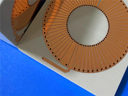
Hi, I'm Sally. Today I'm showcasing a custom PCB built on TFA294—an aerospace-grade ceramic-filled PTFE substrate—with a thick 2.03mm (80mil) core and an OSP finish.
This custom PCB was fabricated using TFA294, a fiberglass-free ceramic-filled PTFE substrate with a dielectric constant of 2.94 at 10 GHz. An 80mil (2.03mm) core was specified, resulting in a 2.1mm finished thickness. An OSP (Organic Solderability Preservative) finish was applied rather than the more common ENIG, keeping the copper surface bare and cost-effective. The 2-net design points to a focused RF component—likely for satellite communications, phased array antennas, or radar systems.
Key Takeaways
- Material: TFA294 — ceramic-filled PTFE, fiberglass-free (Dk 2.94)
- Key Benefit: Excellent frequency stability, minimal dielectric loss, aerospace-grade reliability
- Board Size: 49mm x 90.3mm | Finished Thickness: 2.1mm (80mil core)
- Construction: Double-sided, no solder mask was applied on either side, no silkscreen was used
- Surface Finish: OSP — a bare-copper, cost-effective alternative to ENIG
- Design: 16 components, 7 vias, 2 nets — a focused RF circuit
- Quality: IPC-Class-2 was met, and 100% electrical testing was performed
An RF board was required by our customer that combined a thick 80mil substrate with a bare-copper OSP finish. The thickness was likely specified for mechanical rigidity or specific electrical characteristics, while the OSP finish was chosen for cost efficiency and to avoid the additional metal layers of ENIG. The application demanded aerospace-grade reliability with minimal dielectric loss.
TFA294 was selected from the TFA series. Here's why it was chosen:
Fiberglass-Free Construction
The dielectric layer was composed of PTFE resin and uniformly dispersed nano-ceramics—no glass fiber cloth was used. This eliminated the "fiberglass effect," where weave patterns cause microscopic Dk variations that degrade signal integrity at high frequencies.
Low and Stable Dk (2.94 at 10 GHz)
Excellent frequency stability was achieved, with minimal variation across the operating range. The low TCDK of -5 ppm/°C ensured consistent performance from -55°C to 150°C.
Exceptional Low Loss (Df = 0.0010 at 10 GHz and 20 GHz)
Minimal signal attenuation was ensured—even at 40 GHz, the dissipation factor remained at just 0.0012.
Minimized Anisotropy
X/Y/Z anisotropy was minimized, and the CTE (18 ppm/°C in X/Y axes) was closely matched to copper foil for reliable plated through-holes.
Low Moisture Absorption (0.03%)
Performance drift in humid environments was prevented.
UL 94-V0 Rating
Flame resistance was confirmed for safety-critical applications.

Board Specifications
| Feature |
Specification |
| Dimensions |
49mm x 90.3mm (±0.15mm) |
| Stackup |
35μm Cu / 2.03mm TFA294 / 35μm Cu |
| Finished Thickness |
2.1mm |
| Trace/Space |
6/7 mils |
| Min Hole Size |
0.35mm |
| Surface Finish |
OSP |
| Solder Mask |
None (both sides) |
| Silkscreen |
None |
| Testing |
100% electrical |
| Standard |
IPC-Class-2 |
Design Statistics
| Metric |
Value |
| Components |
16 |
| Total Pads |
31 (18 through-hole, 13 SMT) |
| Vias |
7 |
| Nets |
2 |
The 2-net design indicates a focused RF sub-circuit—likely a filter, coupler, or antenna feed network. The 80mil core is unusually thick for a 2-layer board and suggests specific mechanical or electrical requirements.
OSP Surface Finish
OSP was chosen as a cost-effective, bare-copper finish. Unlike ENIG, no nickel or gold layers were applied, keeping the surface simple and avoiding any potential magnetic or loss contributions from additional metals. OSP protects the copper during storage and soldering while leaving the surface essentially bare.
No Solder Mask (Both Sides)
Solder mask was eliminated to prevent any potential dielectric loss or impedance variation at microwave frequencies.
No Silkscreen
Silkscreen was omitted to keep the board clean and optimize RF performance.
80mil Thick Core
The thick core was specified for mechanical rigidity or specific electrical characteristics—TFA294 is available in a range of thicknesses to meet diverse design needs.
TFA294 Properties
| Property |
Value |
| Dk @ 10 GHz |
2.94 |
| Df @ 10 GHz |
0.001 |
| Df @ 20 GHz |
0.001 |
| Df @ 40 GHz |
0.0012 |
| TCDK |
-5 ppm/°C (-55°C to 150°C) |
| CTE (X/Y/Z) |
18/18/32 ppm/°C |
| Thermal Conductivity |
0.59 W/mK |
| Moisture Absorption |
0.03% |
| Flammability |
UL 94-V0 |
Why This Matters: TFA294 offers exceptional loss performance that remains stable even at 40 GHz, with a TCDK of just -5 ppm/°C. Its fiberglass-free construction ensures superior Dk uniformity compared to woven PTFE materials.
Comparison: How TFA294 Stacks Up
| Property |
TFA294 |
Standard PTFE |
FR-4 |
| Fiberglass |
No |
Usually |
Yes |
| Dk @ 10 GHz |
2.94 |
2.2–3.5 |
4.0–4.5 |
| Df @ 10 GHz |
0.001 |
0.001–0.003 |
0.02–0.03 |
| Df @ 40 GHz |
0.0012 |
Varies |
Poor |
| TCDK |
-5 ppm/°C |
-50 to -150 |
Varies |
| Anisotropy |
Minimized |
Present |
Present |
Why This Matters: TFA294 delivers extremely low and stable loss across a wide frequency range, with minimal anisotropy and excellent thermal stability—ideal for aerospace and high-frequency applications.
Ideal Applications
With its low loss, stable Dk, and aerospace-grade reliability, this design is purpose-built for:
- Aerospace equipment, space, in-cabin equipment, and aircraft
- Microwaves, antennas, and phase-sensitive antennas
- Early warning radars and airborne radars
- Phased array antennas and beamforming networks
- Satellite communications and navigation
- Power amplifiers
Q: Why was OSP chosen instead of ENIG?
A: OSP was chosen for cost efficiency and to keep the copper surface essentially bare. No nickel or gold layers were applied, avoiding any potential magnetic or loss contributions from additional metals.
Q: Why was an 80mil (2.03mm) core specified?
A: The thick core was likely specified for mechanical rig idity or specific electrical characteristics. TFA294 is available in a range of thicknesses to meet diverse design needs.
Q: What makes TFA294 different from standard PTFE?
A: TFA294 uses no fiberglass reinforcement—the dielectric is composed of PTFE resin and nano-ceramics. This eliminates the fiberglass effect and provides superior Dk uniformity and frequency stability.
Q: How does TFA294 perform at higher frequencies?
A: Exceptionally well. The dissipation factor remains at 0.0010 even at 20 GHz and only rises to 0.0012 at 40 GHz, with a TCDK of just -5 ppm/°C.
Q: Why was no solder mask or silkscreen applied?
A: Both were eliminated to prevent any potential dielectric loss or interference with RF performance—critical for sensitive microwave circuits.
Q: Is this material suitable for space applications?
A: Yes. TFA294 is described as an aerospace-grade material with low moisture absorption and UL 94-V0 rating, making it suitable for space and aerospace environments.
Final Thoughts
TFA294 delivers exceptional low-loss performance across a wide frequency range, with a fiberglass-free construction that ensures superior signal consistency. Combined with the cost-effective OSP finish and thick 80mil core, this board is purpose-built for demanding aerospace and RF applications.
Got a high-frequency aerospace project in mind? I'd love to hear about it.


 Your message must be between 20-3,000 characters!