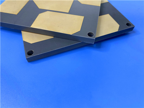
Hi, I'm Sally. Today I'm showcasing a custom PCB built on Wangling F4BME245—a next-generation PTFE composite laminate clad with reverse-treated foil (RTF) copper, engineered for low-PIM, high-precision RF applications.
This custom PCB was fabricated using F4BME245, a PTFE/fiberglass composite laminate clad with RTF copper. An ultra-thin 4mil (0.102mm) core was specified, resulting in a finished thickness of just 0.2mm. With 9 nets and 50 components, this is the most complex circuit topology we've featured—well-suited for feed networks, phased array antennas, and multi-port passive components.

Key Takeaways
- Material: F4BME245 — PTFE composite with woven fiberglass and RTF copper
- Key Benefit: Low PIM, precise fine-line etching, reduced conductor loss, ultra-thin core
- Board Size: 85.6mm x 47mm | Finished Thickness: 0.2mm (ultra-thin)
- Construction: Double-sided, no solder mask was applied on either side, no silkscreen was used
- Surface Finish: Immersion Gold
- Design: 50 components, 34 vias, 9 nets — the most complex topology featured to date
- Quality: IPC-Class-2 was met, and 100% electrical testing was performed
A compact, multi-port RF board was required by our customer for a demanding microwave application. Physical thickness constraints demanded an ultra-thin construction, while the multi-net topology required precise impedance control across several signal paths. Low PIM performance and reduced conductor loss were also essential for the application's signal integrity requirements.
F4BME245 was selected, a high-performance PTFE composite laminate from Wangling.
Reverse-Treated Foil (RTF) Copper Cladding
RTF copper was specified to provide superior low-PIM performance, enable more precise etching for fine-line circuits, and reduce conductor loss. This made it ideal for the high-precision 4/7 mil routing required by the design.
Ultra-Thin Core (0.102mm / 4mil)
An ultra-thin core was used to achieve the 0.2mm finished thickness demanded by the application's physical constraints.
Lower Dielectric Loss Than Predecessor
F4BME245 was engineered to significantly outperform its predecessor, F4B245, offering lower dielectric loss, higher insulation resistance, and enhanced stability.
Controlled Dielectric Constant
The electrical and mechanical properties were precisely tuned by adjusting the ratio of PTFE to fiberglass cloth within the composite. This allowed the dielectric constant to be controlled while low loss characteristics and dimensional stability were maintained.
Improved Dimensional Stability
A higher fiberglass content was used to improve dimensional stability, lower the thermal expansion coefficient, and reduce temperature drift. A marginal increase in dielectric loss was accepted as a balanced trade-off.
Domestic High-Performance Substitute
F4BME245 serves as a reliable, high-performance domestic substitute for comparable imported laminates, reducing supply chain risk.
Board Specifications
| Feature |
Specification |
| Dimensions |
85.6mm x 47mm (±0.15mm) |
| Stackup |
35μm Cu / 0.102mm F4BME245 / 35μm Cu |
| Finished Thickness |
0.2mm (ultra-thin) |
| Trace/Space |
4/7 mils |
| Min Hole Size |
0.5mm |
| Surface Finish |
Immersion Gold |
| Solder Mask |
None (both sides) |
| Silkscreen |
None |
| Testing |
100% electrical |
| Standard |
IPC-Class-2 |
Design Statistics
| Metric |
Value |
| Components |
50 |
| Total Pads |
39 (21 through-hole, 18 SMT) |
| Vias |
34 |
| Nets |
9 |
The 9-net design represents the most complex circuit topology we've featured in this series. Unlike the single-net and 2-net designs covered previously, this board supports multiple signal paths—consistent with a multi-port feed network, phased array element, or a combination of passive components.
No Solder Mask (Both Sides)
Solder mask was eliminated to prevent any potential dielectric loss or impedance variation at microwave frequencies.
No Silkscreen
Silkscreen was omitted to keep the board clean and optimize RF performance.
Immersion Gold Finish
Immersion gold was chosen to deliver a flat, solderable surface with excellent corrosion resistance.
Ultra-Thin 0.2mm Construction
The extreme thinness was achieved through the 4mil core, enabling compact, lightweight designs for space-constrained microwave systems.
Ideal Applications
- Microwave, RF, and Radar systems
- Phase Shifters and Passive Components
- Power Dividers, Couplers, and Combiners
- Feed Networks and Phased Array Antennas
- Satellite Communication and Base Station Antennas
Q: What makes F4BME245 different from F4BME220?
A: F4BME245 is clad with reverse-treated foil (RTF) copper, providing superior low-PIM performance, more precise etching for fine-line circuits, and reduced conductor loss. It also significantly outperforms its predecessor, F4B245.
Q: Why was RTF copper specified?
A: RTF copper was specified for its low-PIM performance, precise etch definition for 4/7 mil traces, and reduced conductor loss—all critical for high-precision RF designs.
Q: Why was an ultra-thin 0.2mm construction specified?
A: The thickness was driven by physical constraints of the application. F4BME245's 4mil core enabled the ultra-thin 0.2mm finished thickness.
Q: What does 9 nets indicate about this design?
A: A 9-net topology represents multiple signal paths—consistent with a multi-port feed network, phased array element, or a combination of passive components.
Q: How is the dielectric constant controlled in F4BME245?
A: The properties are tuned by adjusting the ratio of PTFE to fiberglass cloth. Higher fiberglass content improves dimensional stability and lowers CTE, at a marginal cost in dielectric loss.
Q: Is this material a reliable alternative to imported laminates?
A: Yes. F4BME245 was developed as a high-performance domestic substitute for comparable imported laminates.
F4BME245 delivers low-PIM performance, precise fine-line etching, and reduced conductor loss in an ultra-thin package. Combined with its carefully balanced PTFE-to-fiberglass formulation, it is purpose-built for multi-net feed networks, phased array antennas, and high-precision microwave designs.
Got a low-PIM or multi-net RF project in mind? I'd love to hear about it.


 Your message must be between 20-3,000 characters!